Printing head and three-dimensional printer

A technology of 3D printers and print heads, applied in the direction of additive processing, etc., can solve the problems of large temperature difference, easy deformation, retraction, and overflow of fuses, and achieve the effects of ensuring molding effects, improving printing accuracy, and avoiding adhesion

Active Publication Date: 2016-04-06
PRINT RITE UNICORN IMAGE PROD CO LTD
View PDF9 Cites 12 Cited by
  • Summary
  • Abstract
  • Description
  • Claims
  • Application Information

AI Technical Summary

Problems solved by technology

[0005] see Figure 10 and Figure 11 (a)-(c), because the section of the above print head near the nozzle 01123 is a thin straight hole 01121, after the molding material is extruded from the nozzle 01123, the temperature difference of the fuse is large, and it retracts under the action of internal stress F, which is easy to deform back Shrink to the position around the spout 01123 such as Figure 11 (c) shows that the extruded fuse will condense around the nozzle 01123 and tend to accumulate more, which will affect the printing accuracy and the actual forming effect of the three-dimensional object
In addition, the Teflon tube 0113, throat 0114 and nozzle 0112 of the above-mentioned print head adopt a planar butt joint structure. The butt joint of 0112 is tight, so the molten molding material often overflows undesirably at the butt joint

Method used


Image

  • Printing head and three-dimensional printer
  • Printing head and three-dimensional printer
  • Printing head and three-dimensional printer

Examples


no. 1 example

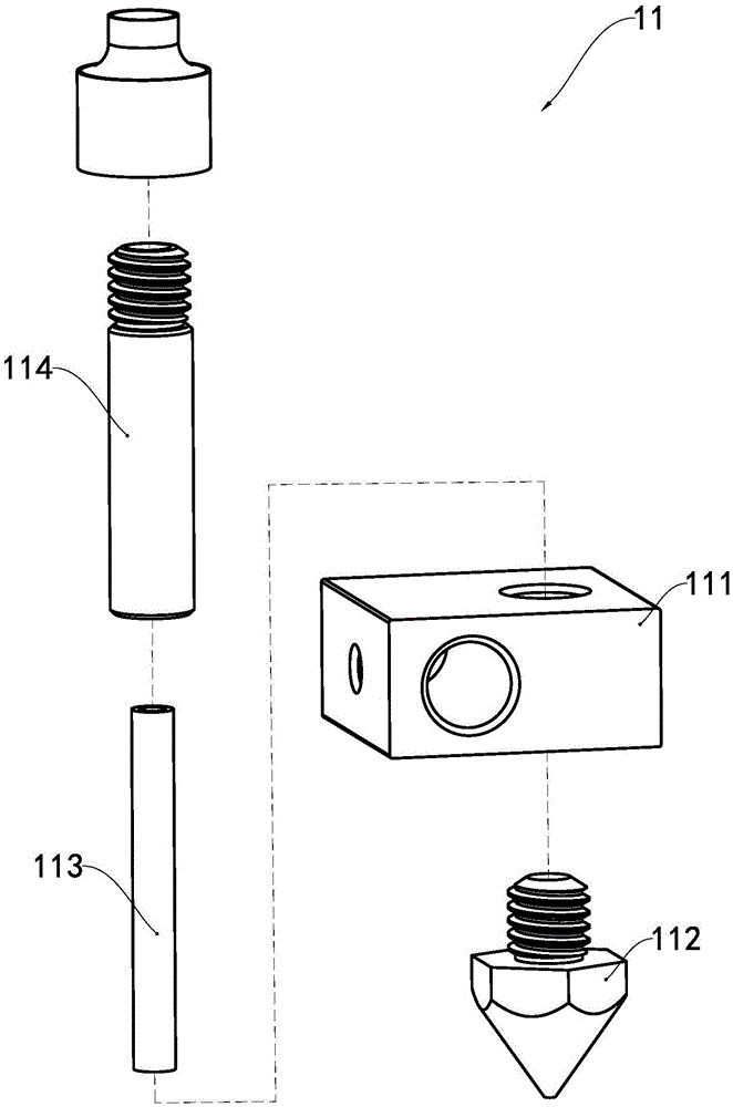
[0035] see image 3 and Figure 4 , the print head 11 of the present embodiment comprises a heating block 111, a throat 114 and a nozzle 112 fixedly connected to the heating block 111, and a Teflon tube 113 coaxially arranged with the throat 114 and being located in the throat 114, and the nozzle 112 The melting pipe 1122 is set as an outwardly expanding conical hole 1121 near the spout 1123. The conical hole 1121 is a turning space formed by the rotation of a straight line around the axis, and the closer the position to the spout 1123 is, the smaller the radius of the conical hole 1121 is. big.

[0036] see Figure 5 and Image 6 , the section near the nozzle of the print head in this embodiment is set as a tapered hole 1121, which expands outward near the nozzle 1123. After the molding material is extruded from the nozzle 1123, due to the low temperature of the external environment, the fuse is subjected to internal stress F after being cooled. The effect of deformation ...

no. 2 example

[0039] As an explanation of the second embodiment of the print head of the present invention, only the differences from the above first embodiment of the print head will be described below.

[0040] Such as Figure 7 As shown in (a) and 7(b), the expansion hole of the melt tube of the nozzle near the nozzle section is a turning space formed by the rotation of a curved section around the axis, and the radius of the expansion hole is larger as it is closer to the nozzle.

no. 3 example

[0042] As an explanation of the third embodiment of the print head of the present invention, only the differences from the above first embodiment of the print head will be described below.

[0043] Such as Figure 8As shown, the expansion hole of the melt tube of the nozzle near the nozzle section is a turning space formed by the rotation of a broken line segment around the axis, and the radius of the expansion hole is larger as it is closer to the nozzle.

[0044] The first embodiment of the three-dimensional printer:

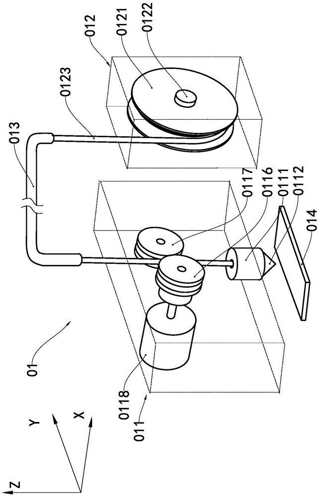
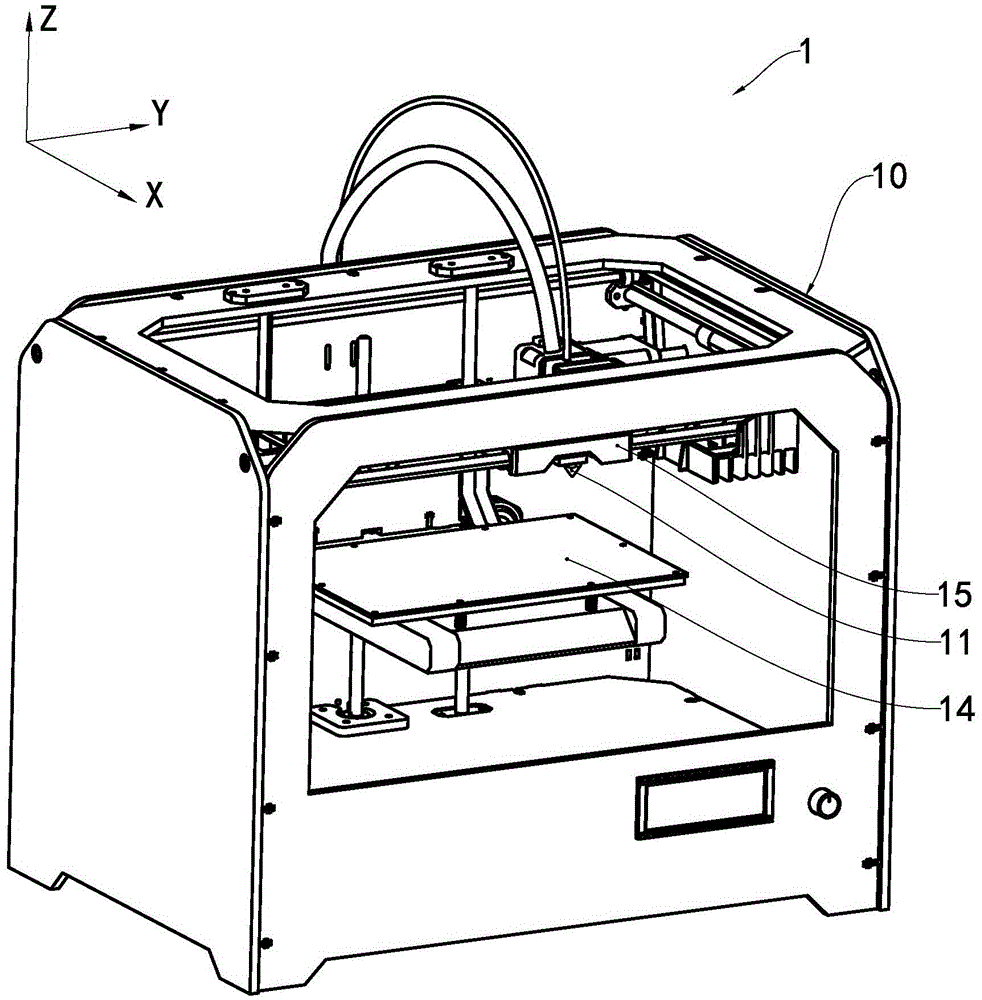
[0045] see figure 2 with Figure 4 , the three-dimensional printer 1 of this embodiment includes a frame 10 , a controller, a printing pallet 14 , and a printing head 11 arranged on a movable carriage 15 . The print head 11 prints a three-dimensional object layer by layer on the print pallet 14 according to the trajectory of the print head 11 moving relative to the print pallet 14 generated by the controller of the three-dimensional printer 1 . The print ...


PUM


Abstract

The invention relates to a printing head for a three-dimensional printer. The printing head comprises a heating block, a throat tube fixedly connected with the heating block and a spraying nozzle, and further comprises a Teflon pipe located in the throat tube in the mode of being coaxial with the throat tube. The section, near a spraying opening, of a melting pipe of the spraying nozzle is a hole expanding outwards. The printing head can effectively prevent extruded fuse wires from adhering and agglomerating to the periphery of the spraying opening, improve printing accuracy and guarantee the forming effect of a three-dimensional object. The invention further provides the three-dimensional printer including the printing head.

Description

technical field [0001] The invention relates to a component of a rapid prototyping device and a rapid prototyping device comprising the component, in particular to a print head for a fused deposition type rapid prototyping device and a three-dimensional printer comprising the print head. Background technique [0002] A three-dimensional printer is a device based on a digital model that uses materials such as powdered metal or plastic to construct three-dimensional objects by layer-by-layer printing. One of the three-dimensional printers is to supply molding materials to the printing head in the form of filaments. The molding materials are heated to a molten state by means of electric heating in the printing head. The moving path prints out the 3D object layer by layer. [0003] The background technology of the patent document whose notification number is CN1216726C describes a kind of three-dimensional printer that supplies molding materials to the printing head in the form...

Claims


Application Information

Patent Timeline
Patent Type & Authority Applications(China)
IPC IPC(8): B29C67/00B22F3/115B33Y30/00
CPCB22F3/115B29C67/00
Inventor 宋道权苏健强
Owner PRINT RITE UNICORN IMAGE PROD CO LTD
Why Eureka
Try Eureka