
Driving structure of overwater lifesaving device

A technology of driving structure and lifesaving device, which is applied in the direction of lifebuoy, transportation and packaging, ship propulsion, etc. It can solve the problems of injury to those who fall into the water, difficulty in getting the lifebuoy life jacket for the person who falls into the water, and complicated water flow in the lifesaving environment, so as to increase the distance and improve the success rate effect

Active Publication Date: 2016-04-06
ZHEJIANG SHENGTAI DEFENSE TECH CO LTD
View PDF9 Cites 2 Cited by
  • Summary
  • Abstract
  • Description
  • Claims
  • Application Information

AI Technical Summary

Problems solved by technology

[0003] The current water lifesaving devices are basically passive. Once an accident occurs, it is difficult for the drowning person to get the lifebuoy or life jacket; at the same time, the water flow in some lifesaving environments is complicated, and it is even more difficult to send the lifebuoy or life jacket to the person who fell into the water.
[0004] In order to solve the above problems, people realize the movement of the life buoy on the water by setting the drive structure on the life buoy at present. It is achieved mainly through the propeller and the rudder to control the direction, and the person who fell into the water will panic during the rescue, so both the propeller and the rudder may cause damage to the person who fell into the water

Method used


Image

  • Driving structure of overwater lifesaving device
  • Driving structure of overwater lifesaving device
  • Driving structure of overwater lifesaving device

Examples


Embodiment 1

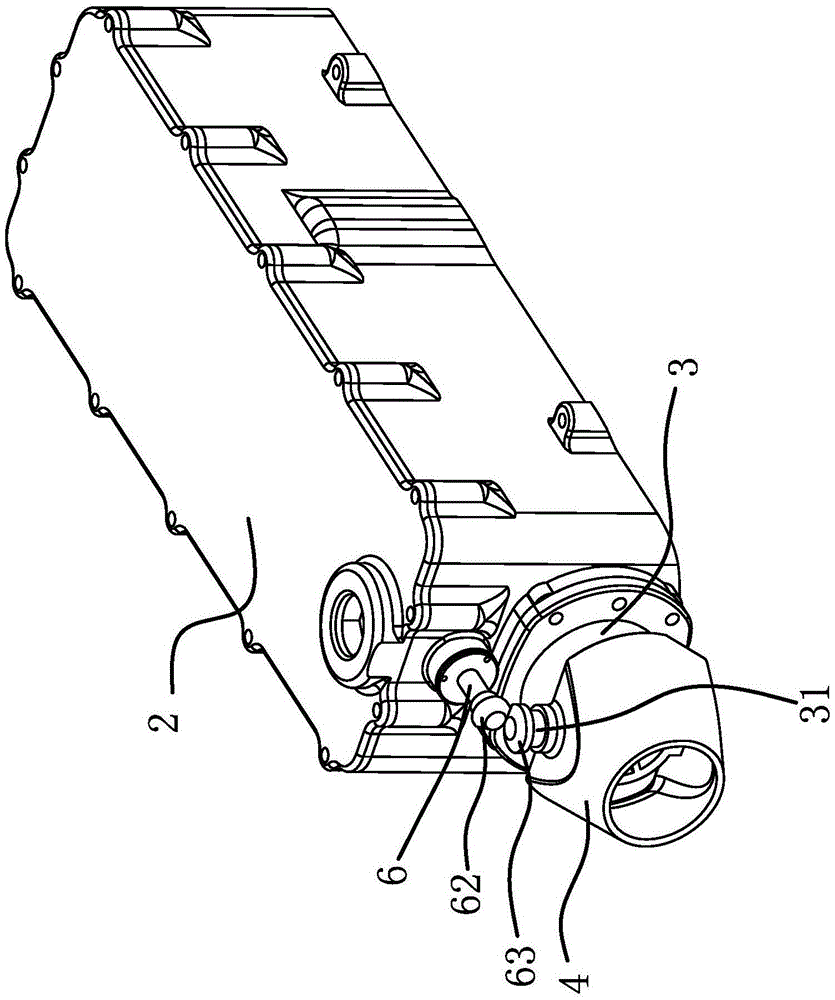
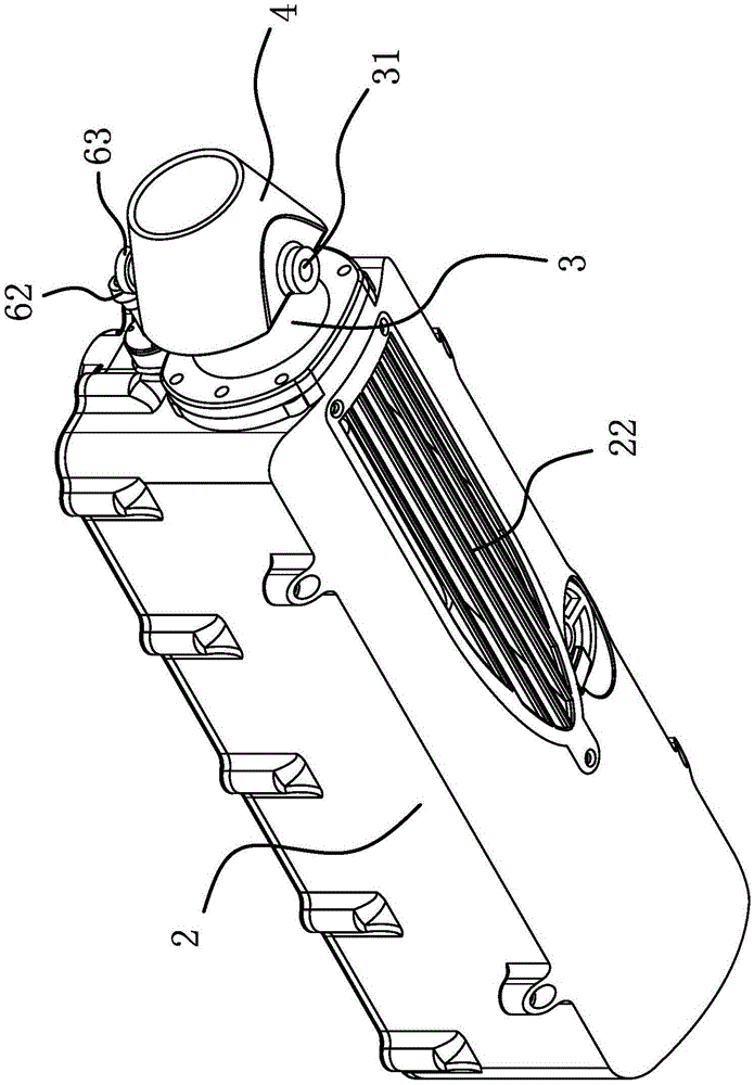
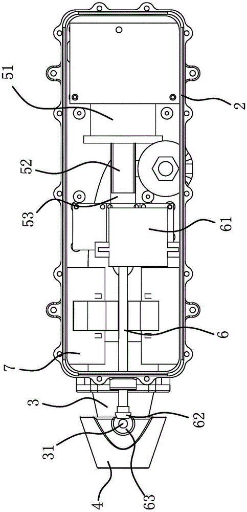
[0027] This example Figure 1 to Figure 6 As shown, the water lifesaving device includes a floating body 1. The floating body 1 is in the shape of a cylinder. The power box 2 is fixed on the buoyant body 1 through the hinge shaft 31 hinged on the diverter sleeve 4 on the collector sleeve 3 .

[0028] The collector sleeve 3 is in the shape of a truncated cone, and the hole wall of the inner hole of the collector sleeve 3 is parallel to its peripheral surface. The end of the collector sleeve 3 with a larger diameter is fixed on the power box 2, and the central axis of the inner hole of the collector sleeve 3 is located at Directly below the central axis of the floating body 1 and parallel to each other. The diversion sleeve 4 is in the shape of a truncated cone, and the hole wall of the inner hole of the diversion sleeve 4 is parallel to its peripheral surface. The end with a smaller diameter of 3 is located in the end with a larger diameter of the inner hole of the diversion ...

Embodiment 2

[0034] The structure and principle of this embodiment are basically the same as that of Embodiment 1, except that the water spray structure includes a water spray motor, the water spray motor is fixed in the power box, and the water inlet pipe connected with the water absorption tank is fixed in the power box. The water inlet pipe is connected with the inlet of the water spray motor, the outlet of the water spray motor is connected with a water outlet pipe, and the water outlet pipe passes through the power box and communicates with the collector sleeve. The water spray motor absorbs water from the water suction tank, and then sprays the water out of the collector sleeve through the water outlet pipe to form a reactionary thrust to push the floating body forward. The way of spraying water will not hurt the drowning person when the floating body is close to the drowning person.

Embodiment 3

[0036] The structure and principle of this embodiment are basically the same as those of Embodiment 1, except that the transmission structure includes a worm gear and a worm, the worm and the steering shaft are coaxially fixed, the steering shaft is located on one side of the hinge shaft, and the turbine is fixed on the hinge shaft , the worm meshes with the turbine. The rotation of the steering shaft drives the worm to rotate, the worm drives the turbine to rotate, and the turbine drives the hinge shaft to rotate to drive the diversion sleeve to swing to realize the steering of the floating body.


PUM


Abstract

The invention provides a driving structure of an overwater lifesaving device, belonging to the field of lifesaving equipment and solving the technical problem that the existing overwater lifesaving device possibly causes injury to people falling into water. The driving structure of the overwater lifesaving device comprises a power box, a collection sleeve fixed at one end of the power box as well as a diversion sleeve communicated with the collection sleeve and articulated on the collection sleeve, wherein a steering shaft is arranged in the power box; the steering shaft is connected with a driving part I capable of driving the steering shaft to rotate; the other end of the steering shaft penetrates through the power box; a transmission structure capable of driving the diversion sleeve to swing along an articulated shaft is arranged between the diversion sleeve and a rotating shaft; a suction sump communicated with the outside is formed in the bottom of the power box; a communication pore is formed in one end, fixed with the collection sleeve, of the power box; two ends of the communication pore are respectively communicated with the suction sump and the collection sleeve; and the power box is provided with a water spraying structure capable of sucking water into the suction sump and enabling the water in the suction sump to be sprayed out of the collection sleeve. The driving structure provided by the invention has the advantage that people falling into water can not be injured when a floating body approaches to the people falling into water.

Description

technical field [0001] The invention belongs to the field of lifesaving equipment, and relates to a water lifesaving device, in particular to a driving structure of the water lifesaving device. Background technique [0002] The water lifesaving device is used to rescue those who fall into the water on the water, and it mainly includes a life buoy and a life jacket. [0003] Current water lifesaving devices are basically passive. Once an accident occurs, it is difficult for the drowning person to get a lifebuoy or a life jacket. [0004] In order to solve the above problems, people realize the movement of the life buoy on the water by setting the drive structure on the life buoy at present. Realize, mainly promote by propeller, and rudder controls direction, and the drowning person can panic when rescue, so propeller and rudder all may cause injury to the drowning person. Contents of the invention [0005] The purpose of the present invention is to solve the above-mention...

Claims


Application Information

Patent Timeline
Patent Type & Authority Applications(China)
IPC IPC(8): B63H11/02B63H11/107B63C9/08
CPCB63C9/08B63H11/02B63H11/107
Inventor 蔡海平金方吉
Owner ZHEJIANG SHENGTAI DEFENSE TECH CO LTD
Learn More