Oil-electric hybrid power multi-rotor aircraft

A technology of multi-rotor aircraft and hybrid electric power, applied in aircraft, rotorcraft, motor vehicles, etc., can solve the problems of limited flight time, small load, short range, etc.

Inactive Publication Date: 2016-04-06
陈蜀乔
View PDF0 Cites 25 Cited by
  • Summary
  • Abstract
  • Description
  • Claims
  • Application Information

AI Technical Summary

Problems solved by technology

[0012] In order to overcome the ubiquitous problems of existing multi-rotor aircraft, that is, short flight range, small load, and limited flight time, the present invention utilizes oil-electric hybrid power to overcome the inherent shortcomings of electric

Method used


Image

  • Oil-electric hybrid power multi-rotor aircraft
  • Oil-electric hybrid power multi-rotor aircraft
  • Oil-electric hybrid power multi-rotor aircraft

Examples


specific Embodiment approach

[0097]DETAILED DESCRIPTION OF THE PREFERRED EMBODIMENTS: The present invention will be further described below in conjunction with the accompanying drawings and embodiments.

example 1

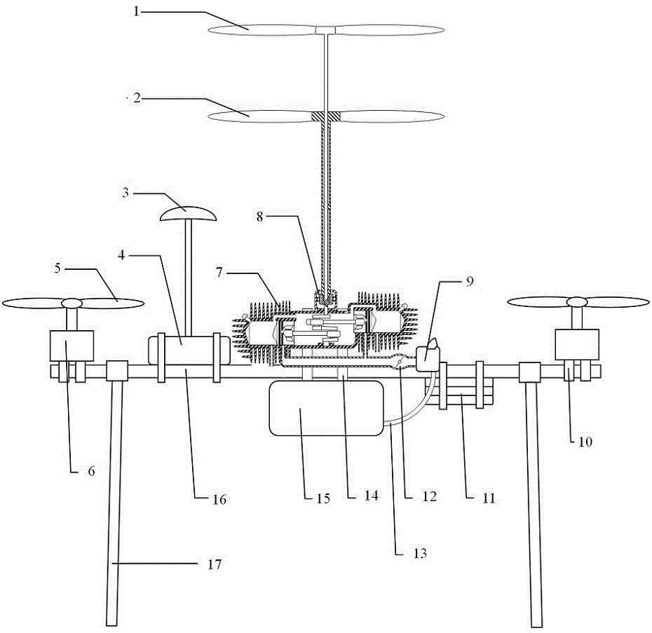
[0098] Example 1: The fuel-electric hybrid aircraft is divided into the main rotor and the auxiliary rotor to provide flight power. The main rotor provides the main lift-off power, and the auxiliary rotor provides a small part of the lift-off power. The main rotor consists of the upper main rotor 1 and the lower main rotor 2. (see figure 1 shown), the upper main rotor shaft 18 passes through the lower main rotor sleeve shaft 19 of the lower main rotor 2 from the top and is welded with the lower bevel gear 21 and then fixed with the power output shaft of the engine. The main shaft of the lower main rotor 2 is the lower The main rotor sleeve shaft 19 has a cavity inside the sleeve shaft, and only the upper, middle and lower end surfaces are in contact with the inner upper main rotor shaft 18 to form constraints, so that the lower main rotor sleeve shaft 19 and the upper main rotor shaft 18 It can rotate independently of each other along the same axis. The lower main rotor sleeve...

example 2

[0099] Example 2: The fuel-electric hybrid aircraft is divided into the main rotor and the auxiliary rotor to provide flight power. The main rotor provides the main lift-off power, and the auxiliary rotor provides a small part of the lift-off power. The main rotor consists of the upper main rotor 1 and the lower main rotor 2. (see figure 1 shown), the upper main rotor shaft 18 passes through the lower main rotor sleeve shaft 19 of the lower main rotor 2 from the top and is welded with the lower bevel gear 21 and then fixed with the power output shaft of the engine. The main shaft of the lower main rotor 2 is the lower The main rotor sleeve shaft 19 has a cavity inside the sleeve shaft, and only the upper, middle and lower end surfaces are in contact with the inner upper main rotor shaft 18 to form constraints, so that the lower main rotor sleeve shaft 19 and the upper main rotor shaft 18 It can rotate independently of each other along the same axis. The lower main rotor sleeve...


PUM


Abstract

The invention relates to an oil-electric hybrid power multi-motor aircraft and belongs to the technical field of unmanned aircrafts. The oil-electric hybrid power multi-motor aircraft is mainly composed of an upper main rotor 1, a lower main rotor 2, a multi-rotor aircraft electric control panel 4, motor-driven auxiliary rotors 5, motors 6, a fuel oil engine 7, a rotating speed pairing gearbox 8, a battery 11 and a throttle control stepping motor 24. Flying power is provided for the aircraft through the main rotors and the auxiliary rotors jointly, the main rotors provide main lifting power, and the auxiliary rotors provide a small part of lifting power; the main rotors are composed of the upper main rotor 1 and the lower main rotor 2, the size of the upper main rotor is the same as the that of the lower main rotor, the rotating speed of the upper main rotor is completely the same as that of the lower main rotor, and the rotating direction of the upper main rotor is opposite to that of the lower main rotor, so that the positive torque and the reverse torque are balanced, and the aircraft is prevented from rotating in the air. The fuel oil engine 7 is fixed to an aircraft arm 16, rotary shafts of the main rotors penetrate through the geometric center of the multi-motor aircraft, and the gravity center of an oil tank 15 is located in the geometric center of the multi-motor aircraft.

Description

technical field [0001] The invention relates to an oil-electric hybrid multi-rotor aircraft, which belongs to the field of non-aircraft. Background technique [0002] The rotor axes of the multi-rotor unmanned aerial vehicle are symmetrically distributed. It is an aircraft that can take off and land vertically, uses four rotors as the power device, and does not carry operators. Its uses are extremely wide. The main applications are as follows [0003] 1. Government agencies: police applications; fire scene command, emergency rescue and disaster relief, traffic management; [0004] 2. Media organizations: news media, aerial photography; [0005] 3 Scientific research institutions: wildlife photography, environmental assessment, aerial archaeology; [0006] 4 Enterprise organization: real estate management, pipeline inspection; [0007] 5 personal applications: remote control flight, aerial photography; [0008] 6 There will be a large number of applications in the logis...

Claims


Application Information

Patent Timeline
IPC IPC(8): B64C27/12B64C27/10
Inventor 陈蜀乔赵成俊马李斌
Owner 陈蜀乔
Why Eureka
Try Eureka