Steel wire rope winding device

A technology of winding device and steel wire rope, which is applied in the direction of winch device and spring mechanism, etc., can solve the problems of high labor intensity, low safety factor, large length, diameter and weight of steel wire rope, etc., so as to reduce labor intensity and improve work efficiency. Efficiency, promotion and application prospects

Active Publication Date: 2016-04-06
HANGANG GRP HANBAO IRON & STEEL +1
View PDF5 Cites 9 Cited by
  • Summary
  • Abstract
  • Description
  • Claims
  • Application Information

AI Technical Summary

Problems solved by technology

[0002] The hoisting equipment wire rope needs to be replaced in time after reaching the end of its service life, but in some heavy industrial production sites, due to the large length, diameter and weight of the wire rope, it is difficult to rewind and discharge the waste wire rope
For example: in the cold rolling production line of metallurgical enterprises, the horizontal looper pulls the wire rope through the hoist to drive the looper car to fill and release the sleeve to realize the storage and release of the strip, so as to ensure the continuous and stable operation of the production line; in the case of the looper wire rope When replacing, because the average length of the wire rope of the looper is about 500m, the diameter is about 44mm, and the weight per 100 meters is about 900 kg, and the horizontal looper cannot use the crane to lift the wire rope for replacement; The normal replacement of sets of steel wire ropes requires 40 to 50 people, and it takes about 8 hours to complete, which seriously affects normal production. At the same time, it is also very difficult to recycle and discharge waste steel wire ropes. Generally, the waste steel wire ropes are cut into about 10m A section of short rope is collected and bundled for waste discharge. The safety factor is low and the labor intensity is high, which is not conducive to the recycling of steel wire rope.

Method used


Image

  • Steel wire rope winding device
  • Steel wire rope winding device
  • Steel wire rope winding device

Examples


Embodiment Construction

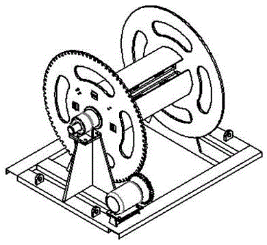
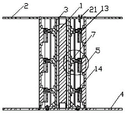
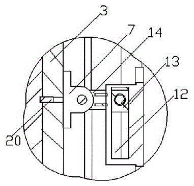
[0026] figure 1 It is shown that the present invention includes a reel device, a reel fixing device, a support and a driving device; Figure 2 to Figure 5It is shown that the reel device includes a mandrel 1, a gear 2 whose side circle center is vertically fixed to one end of the mandrel 1, four rectangular connecting plates 3 of the same size arranged equidistantly along the circumference of the mandrel 1, side plates 4 and connecting plates 3 four sector plates 5 with the same length and equal size; both ends of the mandrel 1 are provided with blind holes along its length direction; the side of the gear 2 is provided with a through hole 6 in the thickness direction and a mounting hole on the same circumference, in the mounting hole Assemble the U-shaped rope clamp 21 through the connecting bolt, which is used to fix the head of the wire rope on the reel device; the rectangular connecting plate 3 is parallel to the mandrel 1, and one of its short sides is fixed to the inner s...


PUM


Abstract

The invention relates to a steel wire rope winding device. The steel wire rope winding device comprises a spool device, spool fixing devices, a bracket and a driving device, wherein the spool device comprises a spindle, a gear of which the side center of a circle is fixedly perpendicular to one end of the spindle, four rectangular connecting plates which are circumferentially distributed along the spindle at equal intervals, a side plate which is connected to the other end of the spindle and four fan-shaped plates; the spool fixing devices are fixed to both opposite sides of the bracket, the spool fixing devices are formed by sliding shafts, shaft sleeves and locking pins which are used for the sliding shafts to be axially positioned in the shaft sleeves, and the sliding shafts are assembled in blind holes in both ends of the spindle, so that the spool device is positioned; the driving device is fixed to the bracket and is driven to be engaged with the gear by a motor, so as to drive the gear to rotate, so that a steel wire rope is wound. According to the steel wire rope winding device, the expansion and contraction of the fan-shaped plates in the radial direction of the gear are realized by utilizing the displacement of the fan-shaped plates in the radial direction of the gear, the winding and waste discharge of the steel wire rope are realized by utilizing the removable side plate, and the winding and waste discharge of steel wire ropes of various sizes can be conveniently and quickly completed, so that the labor intensity is reduced, and additionally, the working efficiency is improved.

Description

technical field [0001] The invention relates to a steel wire rope winding device, which belongs to the technical field of hoisting equipment. Background technique [0002] The wire ropes of hoisting equipment need to be replaced in time after reaching the service life. However, in some heavy industrial production sites, due to the large length, diameter and weight of the wire ropes, it is difficult to rewind and discharge the waste wire ropes. For example: in the cold rolling production line of metallurgical enterprises, the horizontal looper pulls the wire rope through the hoist to drive the looper car to fill and release the sleeve to realize the storage and release of the strip, so as to ensure the continuous and stable operation of the production line; in the case of the looper wire rope When replacing, because the average length of the wire rope of the looper is about 500m, the diameter is about 44mm, and the weight per 100 meters is about 900 kg, and the horizontal loo...

Claims


Application Information

Patent Timeline
Patent Type & Authority Applications(China)
IPC IPC(8): B66D1/00B66D1/28
CPCB66D1/00B66D1/28
Inventor 贾广如秦疆刘振杰刘宝星裴璐鹏董智马磊杨金钰
Owner HANGANG GRP HANBAO IRON & STEEL
Why Eureka
Try Eureka