Fuel pump

A fuel pump and fuel technology, applied in the direction of fuel injection pump, fuel injection device, special fuel injection device, etc., can solve problems such as piston corrosion and fuel pump no longer running.

Active Publication Date: 2016-04-06
MAN ENERGY SOLUTIONS SA
View PDF7 Cites 0 Cited by
  • Summary
  • Abstract
  • Description
  • Claims
  • Application Information

AI Technical Summary

Problems solved by technology

As a result, piston corrosion can eventually develop on the fuel pump, so that the fuel pump can no longer be operated
In addition, piston corrosion can be caused by dirt in the fuel

Method used


Image

  • Fuel pump

Examples


Embodiment Construction

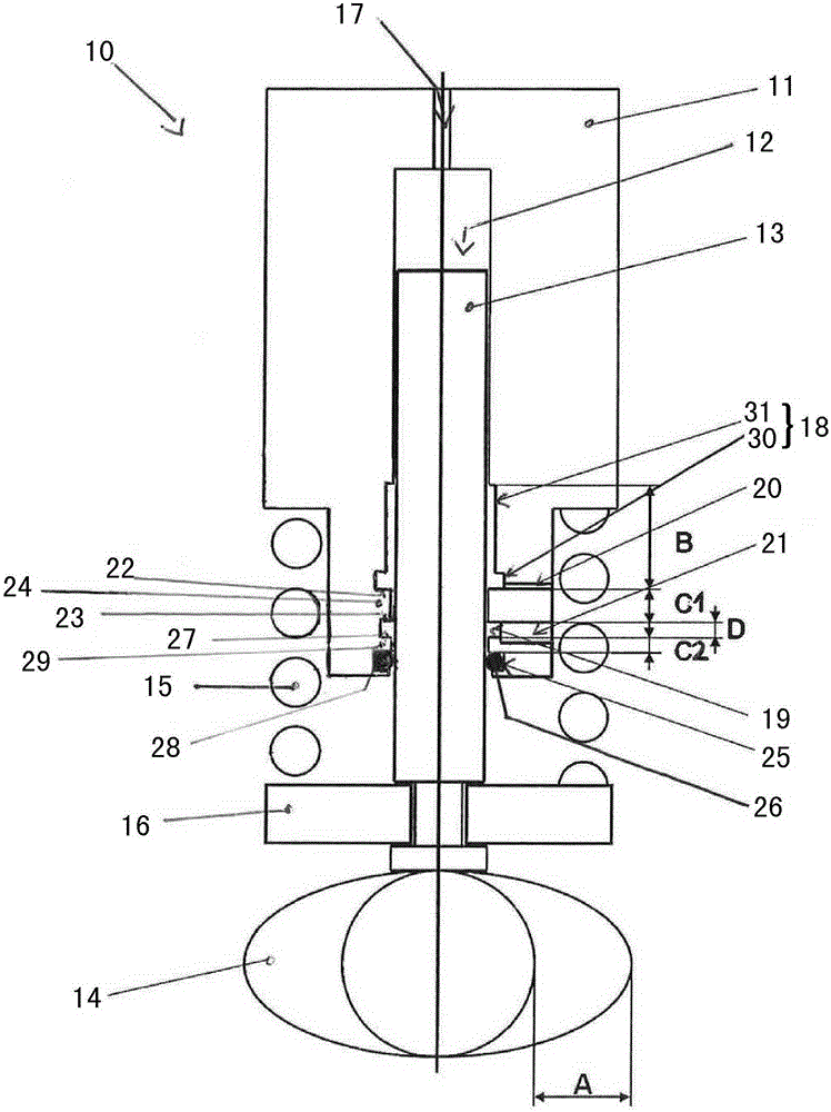
[0016] The invention here relates to a fuel pump, in particular a high-pressure fuel pump for a fuel common rail system of an internal combustion engine operated with heavy fuel oil, such as a marine diesel internal combustion engine.

[0017] figure 1 A cross section of a fuel pump 10 according to the invention is shown, wherein the fuel pump 10 has a pump cylinder 11 and a pump piston 13 movably mounted in a recess 12 of the pump cylinder 11 . The pump piston 13 can move up and down or reciprocate in the gap 12 of the pump cylinder 11 , that is, the movement is controlled by the cam 14 . The cam 14 is also called a driving cam. The movement of the pump piston 13 caused by the cam 14 is counteracted by a restoring force provided by a return spring 15 , also referred to as a drive spring. The drive spring 15 is supported on the one hand on the pump cylinder 11 and on the other hand on a bearing element 16 coupled to the pump piston 13 .

[0018] exist figure 1 The fuel pum...


PUM


Abstract

A fuel pump, in particular a high-pressure fuel pump of a common-rail fuel system, has a pump piston guided in a pump cylinder, wherein, in an area of the pump cylinder within a gap guiding the pump piston, fuel for lubricating and for cooling when necessary is configured with an upper charge groove connected to a first pressure level through at least one charge hole and a lower discharge groove connected to a second pressure level through at least on discharge hole, wherein, a guide sheet for the pump piston is configured between an upper edge of the lower discharge groove and a lower edge of the upper charge groove, and wherein the charge holes leading to the upper charge groove or each charge hole and the lower edge of the upper charge groove adjacently feed into the upper charge groove.

Description

technical field [0001] The invention relates to a fuel pump, in particular to a high-pressure fuel pump of a fuel common rail system. Background technique [0002] The fuel pump has a pump cylinder, wherein a pump piston is movably mounted or guided in the pump cylinder. The pump piston moves up and down in the pump cylinder via one or more cams, whereby fuel is sucked in and delivered by the fuel pump to consumers, and thus, for example, to injection valves of the fuel system. [0003] Fuel pumps known from practice have one or more leakage grooves in the region of the pump cylinder in order to conduct leakage fuel that occurs between the pump cylinder and the pump piston in which the pump piston is movably mounted. In particular, therefore, when a fuel pump lubricated and possibly cooled by fuel oil is used in a fuel system using heavy oil as fuel, since the heavy oil used for lubricating and possibly cooling the fuel pump is in contact with the cam in the area of ​​the ...

Claims


Application Information

Patent Timeline
Patent Type & Authority Applications(China)
IPC IPC(8): F02M59/44F02M59/02
CPCF02M53/00F02M55/00F02M59/442F02M63/0001F02M2200/02F02M2200/06
Inventor D.科瓦莱夫
Owner MAN ENERGY SOLUTIONS SA
Why Eureka
Try Eureka