Compressor and refrigerating cycle device thereof

A technology of a compressor and a compression mechanism, applied in the field of compressors, can solve the problems of reducing the working efficiency of the compressor, reducing the efficiency of the refrigeration cycle device, increasing the superheat degree of the refrigerant in the compression chamber, etc., so as to improve the cooling effect, improve the efficiency, and improve the compression. The effect of efficiency

Active Publication Date: 2016-04-06
GUANGDONG MEIZHI COMPRESSOR +1
View PDF7 Cites 2 Cited by
  • Summary
  • Abstract
  • Description
  • Claims
  • Application Information

AI Technical Summary

Problems solved by technology

[0003] In related technologies, on the one hand, the motor of the compressor generates heat during operation; on the other hand, the compressor discharges high-temperature and high-pressure refrigerant into the casing, and the above two kinds of heat will be transferred to the cylinder of the compressor. The refrigerant in the compression chamber will increase the superheat of the refrigerant in the compression chamber, which will reduce the working efficiency of the compressor, which in turn will reduce the efficiency of the refrigeration cycle device

Method used


Image

  • Compressor and refrigerating cycle device thereof
  • Compressor and refrigerating cycle device thereof
  • Compressor and refrigerating cycle device thereof

Examples


Embodiment 1

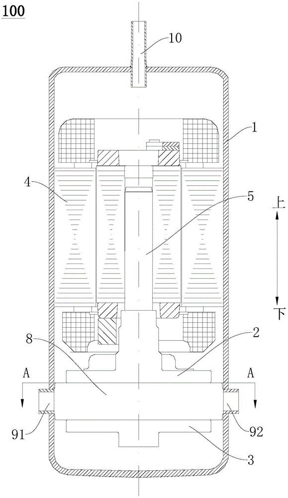
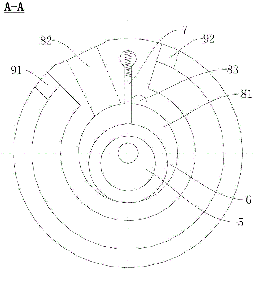
[0051] Such as Figure 1-Figure 4 As shown, in this embodiment, the cylinder assembly may include one cylinder 8 . The main bearing 2 is located at the upper end of the cylinder, and the auxiliary bearing 3 is located at the lower end of the cylinder. The cylinder 8 has a compression chamber 81 , and an air intake port 82 and an exhaust port 83 communicating with the compression chamber 81 are formed on the cylinder 8 .

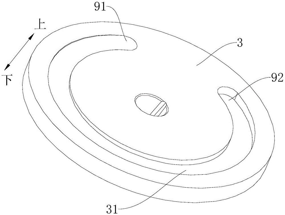
[0052] The inlet 91 of the cooling chamber is located on the side where the air intake 82 is located, and the outlet 92 of the cooling chamber is located on the side where the exhaust port 83 is located. Because the height of the bottom surface of the cooling chamber at the inlet 91 is higher than the height at the outlet 92, that is, the height of the bottom surface of the cooling chamber on the side where the suction port 82 is located is higher than the height on the side where the exhaust port 83 is located, Since the temperature of the refrigerant at t...

Embodiment 2

[0070] Such as Figure 5 and Figure 6 As shown, the difference between the compressor 100 in this embodiment and the first embodiment above is only in the configuration of the cooling cavity. Other structures of the compressor 100 in this embodiment are substantially the same as those in the first embodiment above, and will not be repeated here.

[0071] refer to Figure 5 and Figure 6 and combine figure 1 and figure 2 A second groove 32 is formed on at least one of the main bearing 2 , the cylinder assembly and the auxiliary bearing 3 . The second groove 32 is substantially the same as the first groove 31 in the first embodiment in terms of setting position and molding method, except that the bottom surface of the second groove 32 is a plane, and the bottom wall of the second groove 32 is flat. A bottom structure 33 is provided on it, and the bottom surface of the cooling chamber is the upper surface of the bottom structure 33 at this time. Thereby, the bottom surfa...


PUM


Abstract

The invention discloses a compressor and a refrigerating cycle device thereof. The compressor comprises a housing, a compression mechanism and a condensing device, wherein the compression mechanism is arranged in the housing; the compression mechanism comprises a primary bearing, an air cylinder assembly and a secondary bearing; the primary bearing and the secondary bearing are respectively arranged at the axial two ends of the air cylinder assembly; the air cylinder assembly comprises at least one air cylinder which is provided with a compression cavity; an air suction opening and an air exhaust opening which are communicated with the compression cavity are formed in the air cylinder; at least one cooling cavity is formed in the compression mechanism; the cooling cavity is provided with an inlet and an outlet; the height of the bottom surface, at the inlet, of the cooling cavity is greater than the height of the bottom surface, at the outlet, of the cooling cavity; the condensing device is arranged outside the housing; and the two ends of the condensing device are respectively communicated with the inlet and the outlet. According to the compressor disclosed by the invention, the compression mechanism can be cooled by virtue of the cooling cavity and the condensing device, so that the compression efficiency of the compressor can be improved.

Description

technical field [0001] The invention relates to the field of compressors, in particular to a compressor and a refrigeration cycle device having the same. Background technique [0002] At present, as the country's requirements for the energy efficiency level of refrigeration cycle devices are getting higher and higher, various manufacturers are developing energy-efficient refrigeration cycle devices. The existing refrigeration cycle includes four core components: compressor, evaporator, condenser, and throttling device. From the point of view of the refrigeration principle, the improvement of the heat exchange efficiency of the evaporator and condenser and the improvement of the throttle efficiency of the throttling device can increase the cooling capacity or heating capacity of the refrigeration device, and the improvement of the efficiency of the compressor can reduce the input power of the entire refrigeration equipment. Therefore, improving the performance of these four ...

Claims


Application Information

Patent Timeline
Patent Type & Authority Applications(China)
IPC IPC(8): F04B39/06
CPCF04B39/06
Inventor 程惠鹏
Owner GUANGDONG MEIZHI COMPRESSOR
Why Eureka
Try Eureka