
A steering gear isolation bypass valve group

A technology for isolating bypass and valve group, which is used in mechanical equipment, servo motor components, fluid pressure actuating devices, etc., and can solve the problems of limited flow capacity of spool valve, high precision requirements of spool valve, and difficult to overcome hydraulic control force. , to achieve strong adaptability, solve large leakage of slide valve, and achieve good rudder stabilization effect.

Active Publication Date: 2017-09-01
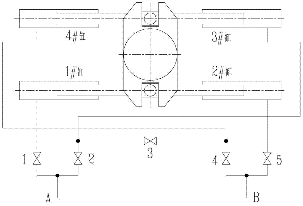
SHANGHAI MARINE EQUIP RES INST
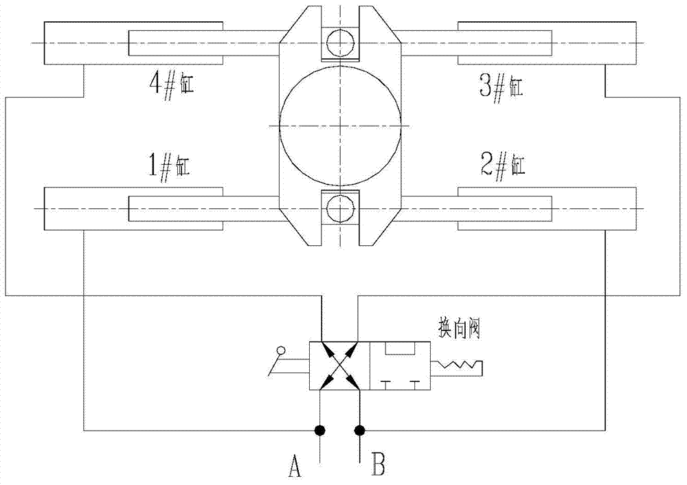
View PDF12 Cites 0 Cited by
  • Summary
  • Abstract
  • Description
  • Claims
  • Application Information

AI Technical Summary

Problems solved by technology

The pipeline of this scheme is relatively simple and the structure is relatively simple, but the slide valve has limited flow capacity and large leakage. When the system flow is large, problems such as volume increase and hydraulic control force are difficult to overcome, and the slide valve High precision requirements and difficult processing

Method used


Image

  • A steering gear isolation bypass valve group
  • A steering gear isolation bypass valve group
  • A steering gear isolation bypass valve group

Examples


Embodiment Construction

[0038] The present invention will now be described in further detail with reference to the drawings.

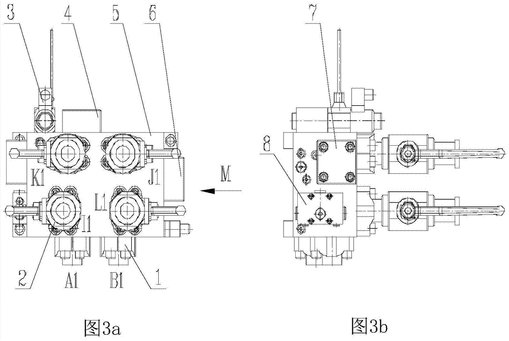
[0039] The structure of the steering gear isolation bypass valve group of the present invention is shown in Fig. 3, including: flange 1, ball valve 2, electromagnetic reversing valve 3, first cartridge valve 4, main valve body 5, and second cartridge valve 6. The third cartridge valve 7, the one-way valve assembly 8.

[0040] The main valve body 5 is used to install various parts, and there are valve fitting holes and hydraulic oil circulation holes inside;

[0041] There are two flanges 1, which are installed on the bottom surface of the main valve body 1 by screws to provide interfaces A1 and B1 for connecting with the main oil pump;

[0042] There are four ball valves 2, which are fixed on the main valve body 5 by screws, and provide ports I1, K1, L1, and J1 for connecting with the rudder steering mechanism. The A1 port of the valve group communicates with I1 and K1 ports, and the...


PUM


Abstract

The invention provides a steering engine isolating bypass valve group. A main valve body of the steering engine isolating bypass valve group provides a port A1 and a port B1 which are connected with a main oil pump; ball valves provide a port I1, a port K1, a port L1 and a port J1 which are connected with a steering engine, the port A1 is communicated with the port I1and the port K1, and the port B1 is communicated with the port L1 and the port J1; when four oil cylinders work at the same time, an electromagnetic directional valve is not energized, control oil passes through the electromagnetic directional valve and then acts on a first cartridge valve so that the first cartridge valve can be closed, and control oil in control oil cavities of second and third cartridge valves returns to an oil tank through the electromagnetic directional valve and an oil drainage port G1 so that the second cartridge valve and the third cartridge valve can be opened; when isolation bypassing needs to be performed on the third oil cylinder, the fourth oil cylinder and corresponding pipe systems of the third and fourth oil cylinders, the electromagnetic directional valve is powered on and a valve element of the electromagnetic directional valve is switched to a left function position to work, control oil passes through the electromagnetic directional valve and acts on the control oil cavities of the second and third cartridge valves so that the second and third cartridge valves can be closed, and a control cavity of the first cartridge valve is communicated with the oil drainage port G1 through the electromagnetic directional valve so that the first cartridge valve can be opened. By means of the steering engine isolating bypass valve group, the functions of oil fluid shunting and isolation bypassing are achieved, a plug-in mode is adopted, the integration level and standardization level are high, and manufacturing is simple.

Description

Technical field [0001] The invention relates to the field of ships, in particular to a steering gear isolation bypass valve group. Background technique [0002] According to the requirements of the standard, two sets of important piping systems should be provided for the steering gear with two sets of power units. When the steering gear has a single failure, it should be able to isolate it and restore the steering ability as soon as possible. [0003] The steering gear isolation bypass valve group is connected between the main control valve group and the rudder steering mechanism, and is used to realize the isolation bypass when a single failure occurs in the oil cylinder or important pipe system. The existing isolation bypass function is mainly implemented by the following two technical solutions: [0004] a. Use multiple manual stop valves to cooperate with operation (see figure 1 ). [0005] b. Use a dedicated reversing valve to achieve (see figure 2 ). [0006] The working princi...

Claims


Application Information

Patent Timeline
Patent Type & Authority Patents(China)
IPC IPC(8): F15B13/06
CPCF15B13/06
Inventor 俞志刚张鸿皓毛立峰董明曦邱大宝
Owner SHANGHAI MARINE EQUIP RES INST
Learn More