Multi-station weighing machine and method

A weighing machine and multi-station technology, used in weighing, measuring devices, instruments, etc., can solve the problems of no weighing accuracy, no feeding speed, overflow and leakage of screw nozzles, etc. The effect of weighing accuracy, reducing weighing error and improving weighing speed

Active Publication Date: 2016-04-06
ZHUHAI HUALI FRICTION MATERIAL
View PDF7 Cites 7 Cited by
  • Summary
  • Abstract
  • Description
  • Claims
  • Application Information

AI Technical Summary

Problems solved by technology

[0005] At present, the automatic weighing feeders provided by various professional automation companies in the market, whether it is a single-screw structure, a twin-screw structure, or a large and small twin-screw structure, cannot p

Method used


Image

  • Multi-station weighing machine and method
  • Multi-station weighing machine and method
  • Multi-station weighing machine and method

Examples


Example Embodiment

[0050] Example one

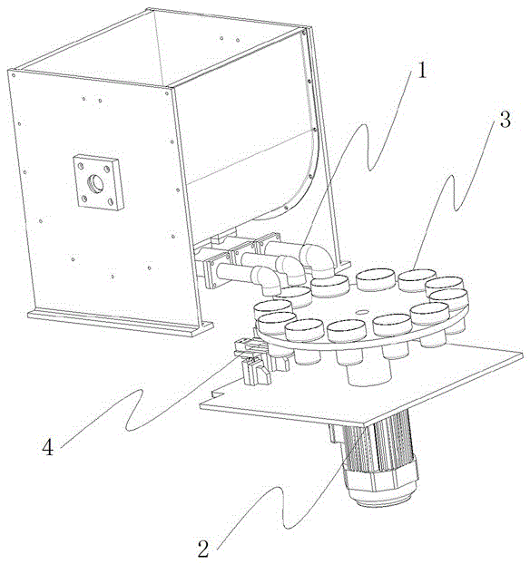
[0051] The feeding device group 1 is composed of two feeding devices. The conveying device is located under the feeding device. The sensor group 4 is composed of two weighing sensors. Each weighing sensor is located under the corresponding feeding device. Each weighing sensor is installed. On the fixed plate 22 of the conveying device 2. When the conveying device 2 steps by one station distance, there will be a material weighing container 3 set on a weighing sensor, and the supporting pallet 5 will evenly transfer the gravity of the material weighing container 3 to the weighing sensor; The control system can analyze whether there is a material weighing container 3 above and whether the added weight reaches the preset value by monitoring the weight on the load cell; when the first material weighing container 3 is transported to the first feeding device 11 Below the discharge port, the control system controls the first feeding device 11 for forward rotation an...

Example Embodiment

[0052] Example two

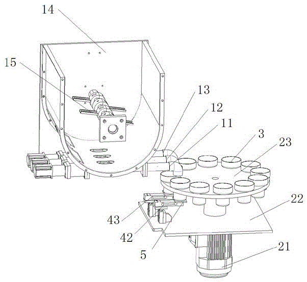
[0053] The feeding device group is composed of three feeding devices, namely the first feeding device 11, the second feeding device 12 and the third feeding device 13. The conveying device 2 is arranged under the feeding device, and the sensor group 4 is composed of two load cells. They are the second load cell 42 and the third load cell 43 respectively. The second load cell 42 is located below the second feeding device 12, and the third load cell 43 is located below the third feeding device 13, each The load cells are all installed on the fixed plate 22 of the conveying device 2. When the conveying device 2 steps by one station distance, there will be a material weighing container 3 set on a weighing sensor, and the supporting pallet 5 will evenly transfer the gravity of the material weighing container 3 to the weighing sensor; The control system can analyze whether there is a material weighing container 3 above and whether the added weight reaches the pres...

Example Embodiment

[0054] Example three

[0055] The feeding device group 1 is composed of three feeding devices, namely a first feeding device 11, a second feeding device 12, and a third feeding device 13; the sensor group 4 is composed of three sensors, respectively A first load cell corresponding to the position of the first feeding device 11, a second load cell 42 corresponding to the position of the second feeding device 12, and a third load cell 43 corresponding to the position of the third feeding device 13. The control system controls the conveying device 2 to step by one station distance at intervals. When the material weighing container 3 is conveyed to the position below the discharge port of the first feeding device 11, the control system controls the first feeding device 11 to rotate and discharge materials. The system detects the increased weight of the material weighing container 3 through the first weighing sensor. When the increased weight of the material weighing container 3 reach...


PUM


Abstract

The invention discloses a multi-station weighing machine and method. The multi-station weighing machine is provided with a feeding device group, a conveying device, a material weighing container group and a control system. The feeding device group is provided with at least two feeding devices, and each feeding device is provided with a material inlet and a material outlet. The conveying device is provided with a plurality of conveying stations which are successively arranged in the arranging direction of the material outlet. The material weighing container group is composed of a plurality of material weighing containers, and each material weighing container is correspondingly installed on one conveying station. The control system is provided with a control module and a sensor group electrically connected with the control module, and the control module is electrically connected with the feeding device group and the conveying device. The multi-station weighing machine has the advantages that the weighing speed is high, the weighing precision is high, material overflow is prevented, the size is small, the cost is low, the operation is easy, the structure is simple, the maintenance is simple, etc.

Description

technical field [0001] The invention relates to a multi-station weighing machine and a method. Background technique [0002] In the brake pad manufacturing industry, the friction material is a mixture of various materials, including tiny particles that are easy to fly, minerals with a large proportion, and fiber and resin materials. Therefore, the friction material is a mixed material with poor fluidity, large compression ratio and large difference in apparent specific gravity. The weight of the friction material on the uniform and stable brake pad is one of the factors restricting the quality of the brake pad. [0003] In the past, the weighing of friction materials in this industry was carried out manually on the electronic weighing platform. In this mode of operation, the quality is subject to the operator's working habits and mentality, and at the same time, the dust caused by the operation brings potential safety hazards of occupational diseases to the operator. Real...

Claims


Application Information

Patent Timeline
IPC IPC(8): G01G19/32G01G19/34
CPCG01G19/32G01G19/346
Inventor 颜钟华肖新建赖志强潘俊圭
Owner ZHUHAI HUALI FRICTION MATERIAL
Why Eureka
Try Eureka