A low-sidelobe emission directional diagram design method improving DOA estimated performance of a MIMO radar

A technology of emission pattern and design method, applied in radio wave measurement systems, instruments, etc., can solve problems such as affecting the accuracy of target angle estimation, reducing the signal-to-noise ratio of the receiving end, and low gain characteristics.

Active Publication Date: 2016-04-06
THE PLA INFORMATION ENG UNIV
View PDF4 Cites 38 Cited by
  • Summary
  • Abstract
  • Description
  • Claims
  • Application Information

AI Technical Summary

Problems solved by technology

[0006] Aiming at the problem in the prior art that the low-gain characteristic of transmitting orthogonal waveforms to form a direction diagram reduces the signal-to-noise ratio at the receiving end, thereby affecting the accuracy of target angle estimation, the present invention proposes a low-sidelobe transmission direction that improves the DOA estimation performance of MIMO radar graph design method

Method used


Image

  • A low-sidelobe emission directional diagram design method improving DOA estimated performance of a MIMO radar
  • A low-sidelobe emission directional diagram design method improving DOA estimated performance of a MIMO radar
  • A low-sidelobe emission directional diagram design method improving DOA estimated performance of a MIMO radar

Examples


Embodiment 1

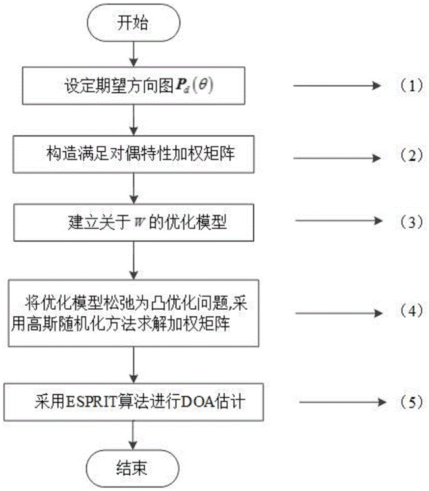
[0046] Embodiment 1, combining Figure 1-Figure 7 , a low sidelobe emission pattern design method for improving MIMO radar DOA estimation performance, the emission pattern design method comprises the following steps:

[0047] Step 1: Set the desired emission pattern; set the desired pattern P d The specific method of (θ) is as follows: according to the airspace angle coverage of the pattern is a certain airspace including the azimuth of the target, the entire airspace is divided into the main lobe area and sidelobe regions Indicates the discretization angle in the main lobe region, Indicates the discretization angle in the sidelobe region.

[0048] Step 2: Make the column vector of the beam domain weighting matrix satisfy the dual property, and ensure that the signal at the receiving end satisfies the rotation invariance; the specific method is: in order to make the receiving array not constrained by the uniform linear array, and at the same time make the received signal...

Embodiment 2

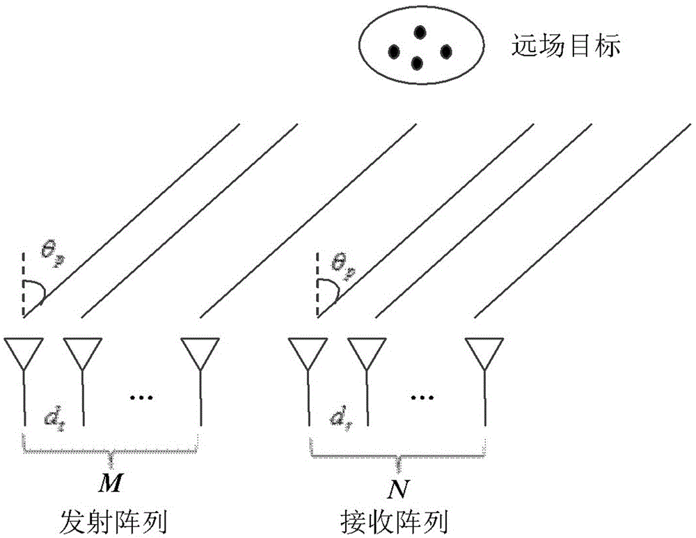
[0070] Example 2: Combining Figure 1-Figure 7 ,Such as figure 1 The structure of the MIMO radar system is shown, assuming that the transmitting array element is M and the receiving array element is N MIMO radar, and the distance between the array elements is d t and d r , the distance between the transmitting array and the receiving array is relatively close. Assuming that the target is located in the far field, the distance from the target to the array is much greater than the array aperture, and the observation angles of the receiving and transmitting arrays to the target are the same. Assume that there are P targets in the area of ​​interest in the space, and the orientations are [θ 1 ,…,θ P ].

[0071] The transmission energy of MIMO radar adopting orthogonal waveform is uniformly distributed in the whole space, but the targets of interest are usually concentrated in a small airspace, and omnidirectional transmission will cause energy waste. In order to focus the tr...


PUM


Abstract

The invention relates to a low-sidelobe emission directional diagram design method improving DOA estimated performance of a MIMO radar. The method comprises the following steps: setting an interesting area; ensuring column vectors of a beam space weighting matrix to satisfy pairing characteristics; ensuring signals at a receiving end to satisfy rotation invariance; constructing an optimized model of a beam space weighting matrix with directional diagram coupling characteristics, rotation invariance of the signals and equality of various array element emission powers as constraint conditions; introducing an auxiliary variable and relaxing a rank-1 constraint to be a positive semidefinite constraint through utilization of the semidefinite relaxing technology; and through utilization of an interior point method, obtaining an optimal solution of the relaxing problem; through a Gaussian randomization method, the beam space weighting matrix is solved; and DOA estimation is carried out on a target at the receiving end through the ESPRIT algorithm. The MIMO radar waveform design technology which is good in performance in the invention can raise the signal to noise ratio at the receiving end, provide an important theoretical basis and a specific realization method for raising the precision of MIMO radar angle estimation.

Description

technical field [0001] The invention belongs to the waveform design technology of MIMO radar in the field of aerospace target reconnaissance, and more specifically relates to a low side lobe emission pattern design method for improving the DOA estimation performance of MIMO radar. Background technique [0002] The waveform design method involved in the present invention designs the MIMO radar transmission signal through the beam domain preprocessing technology, making it close to the desired transmission pattern, reducing the pattern side lobe, and better concentrating the transmission energy on the interested airspace, thereby Improve the signal-to-noise ratio of the received signal. Compared with the existing methods, the DOA estimation accuracy of the target is improved. [0003] The biggest difference between MIMO radar and traditional phased array radar is that MIMO radar has the capability of waveform diversity. Therefore, the performance of MIMO radar in multiple sig...

Claims


Application Information

Patent Timeline
Patent Type & Authority Applications(China)
IPC IPC(8): G01S7/28
CPCG01S7/2813
Inventor 任修坤李玉翔郑娜娥陈松王志民赵远王盛
Owner THE PLA INFORMATION ENG UNIV
Why Eureka
Try Eureka