A Low Sidelobe Transmit Pattern Design Method for Improving the DoA Estimation Performance of MIMO Radar
A technology of transmitting pattern and design method, which is applied in the direction of radio wave measurement system, instrument, etc., can solve the problems affecting the target angle estimation accuracy, low gain characteristics, reducing the signal-to-noise ratio of the receiving end, etc., so as to reduce the computational complexity and improve the Effect of SNR and Sidelobe Suppression
- Summary
- Abstract
- Description
- Claims
- Application Information
AI Technical Summary
Problems solved by technology
Method used
Image
Examples
Embodiment 1
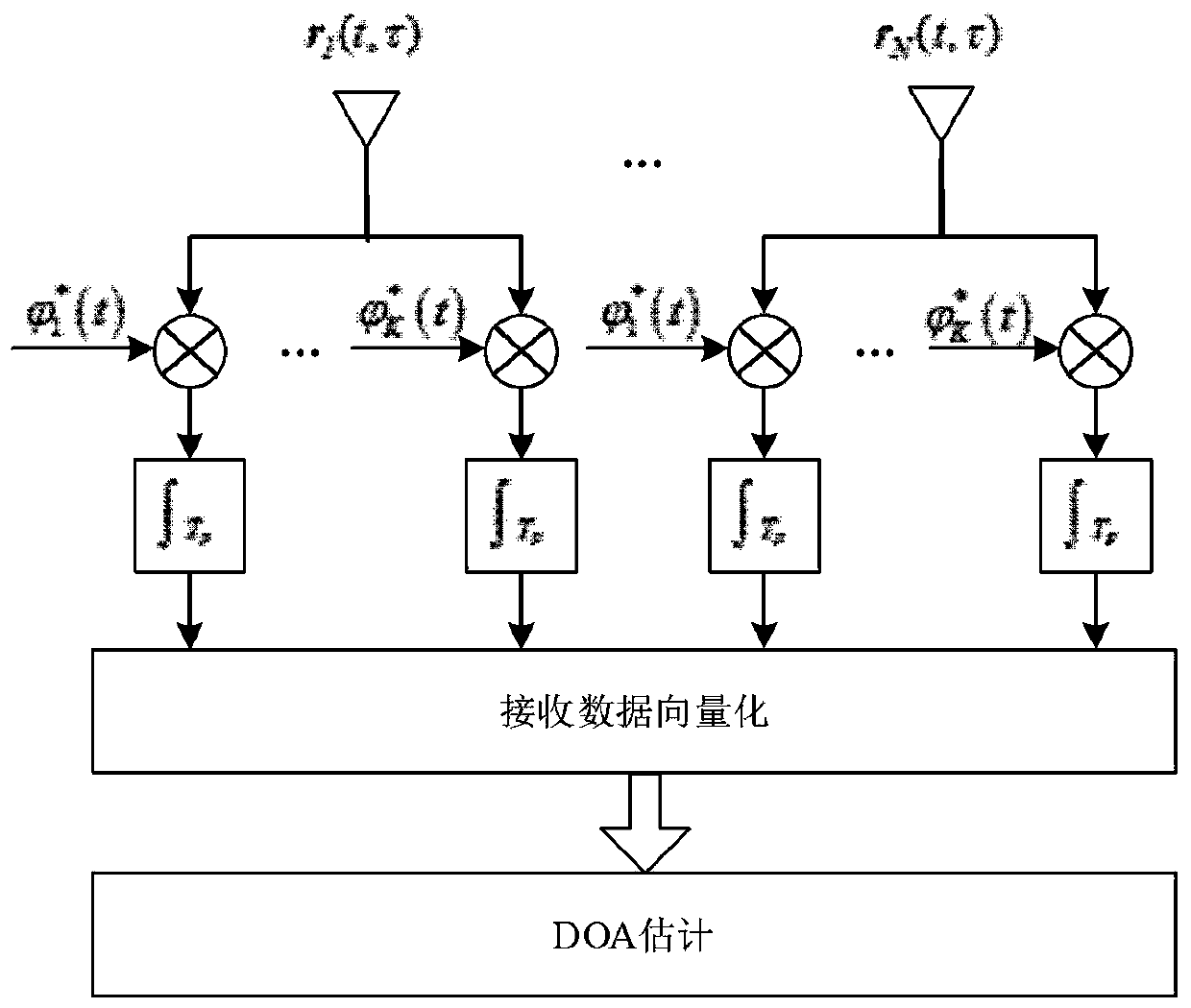
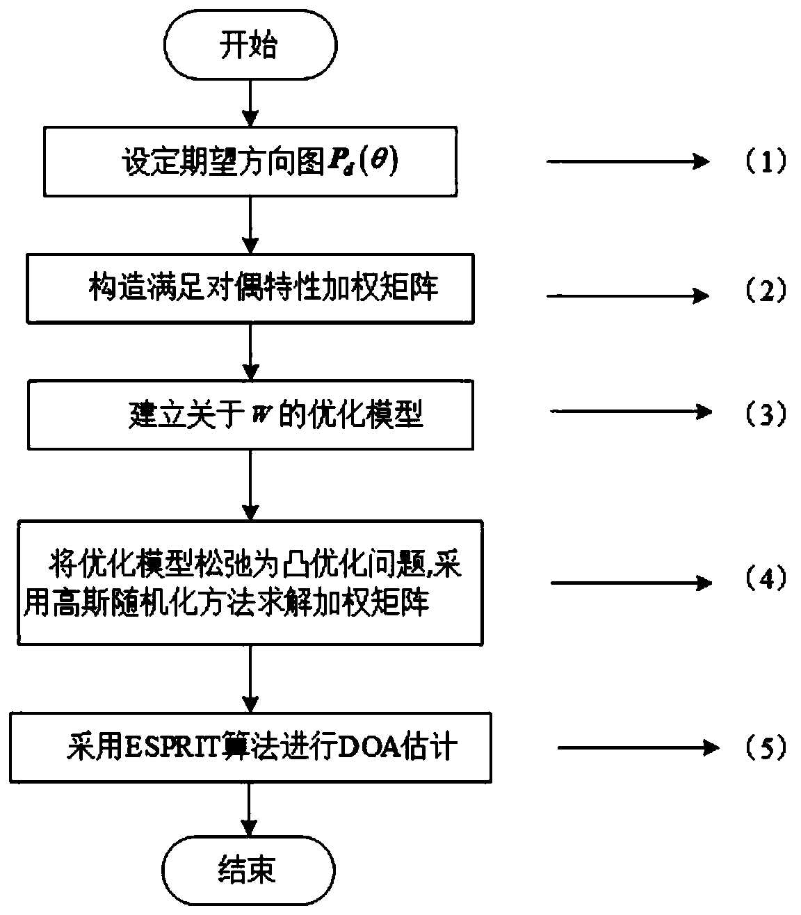
[0046] Embodiment 1, combining Figure 1-Figure 7 , a low sidelobe emission pattern design method for improving MIMO radar DOA estimation performance, the emission pattern design method comprises the following steps:
[0047] Step 1: Set the desired emission pattern; set the desired pattern P d The specific method of (θ) is as follows: according to the airspace angle coverage of the pattern is a certain airspace including the azimuth of the target, the entire airspace is divided into the main lobe area Θ and the side lobe area θ l ∈Θ, (l=1,...,L) represents the discretization angle in the main lobe area, Indicates the discretization angle in the sidelobe region.
[0048] Step 2: Make the column vector of the beam domain weighting matrix satisfy the dual property, and ensure that the signal at the receiving end satisfies the rotation invariance; the specific method is: in order to make the receiving array not constrained by the uniform linear array, and at the same time ma...
Embodiment 2
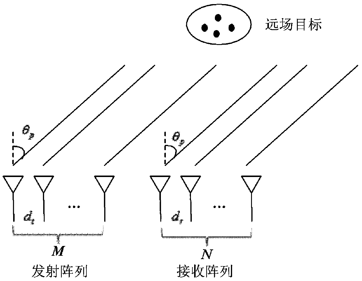
[0069] Example 2: Combining Figure 1-Figure 7 ,Such as figure 1 The structure of the MIMO radar system is shown, assuming that the transmitting array element is M and the receiving array element is N MIMO radar, and the distance between the array elements is d t and d r , the distance between the transmitting array and the receiving array is relatively close. Assuming that the target is located in the far field, the distance from the target to the array is much greater than the array aperture, and the observation angles of the receiving and transmitting arrays to the target are the same. Assume that there are P targets in the area of interest in the space, and the orientations are [θ 1 ,…,θ P ].
[0070] The transmission energy of MIMO radar adopting orthogonal waveform is uniformly distributed in the whole space, but the targets of interest are usually concentrated in a small airspace, and omnidirectional transmission will cause energy waste. In order to concentrate ...
PUM
 Abstract
Description
Claims
Application Information
 - R&D
- Intellectual Property
- Life Sciences
- Materials
- Tech Scout
- Unparalleled Data Quality
- Higher Quality Content
- 60% Fewer Hallucinations
Browse by: Latest US Patents, China's latest patents, Technical Efficacy Thesaurus, Application Domain, Technology Topic, Popular Technical Reports.
© 2025 PatSnap. All rights reserved.Legal|Privacy policy|Modern Slavery Act Transparency Statement|Sitemap|About US| Contact US: help@patsnap.com


