
Curved-surface bionic compound eye imaging device for zoom lens array

A lens array, bionic compound eye technology, applied in the directions of lenses, optics, instruments, etc., can solve the problems of reduced imaging quality, poor resolution, difficult optical splicing, etc., to achieve easy manufacturing and maintenance, avoid out-of-focus state, and easy miniaturization. Effect

Inactive Publication Date: 2016-04-06
CHANGCHUN INST OF OPTICS FINE MECHANICS & PHYSICS CHINESE ACAD OF SCI
View PDF4 Cites 30 Cited by
  • Summary
  • Abstract
  • Description
  • Claims
  • Application Information

AI Technical Summary

Problems solved by technology

[0006] In order to solve the existing hemispherical surface image sensor array bionic compound eye, there are many shortcomings such as complex overall structure, difficult optical splicing, low computing efficiency, poor resolution, high production cost, and is not conducive to miniaturization and light weight; on the other hand, Simply using a planar image sensor as the focal plane of the spherical bionic lens array will cause the lens located at the edge of the field of view to be in a defocused state, and its imaging quality will drop sharply, which in turn will cause the field of view of the compound eye system to be limited, unable to expand and meet The technical problem of actual demand, the present invention provides a curved surface bionic compound eye imaging device with progressive focal length lens array

Method used


Image

  • Curved-surface bionic compound eye imaging device for zoom lens array
  • Curved-surface bionic compound eye imaging device for zoom lens array
  • Curved-surface bionic compound eye imaging device for zoom lens array

Examples


Embodiment Construction

[0022] The present invention will be described in further detail below in conjunction with the accompanying drawings.

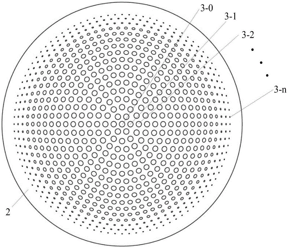
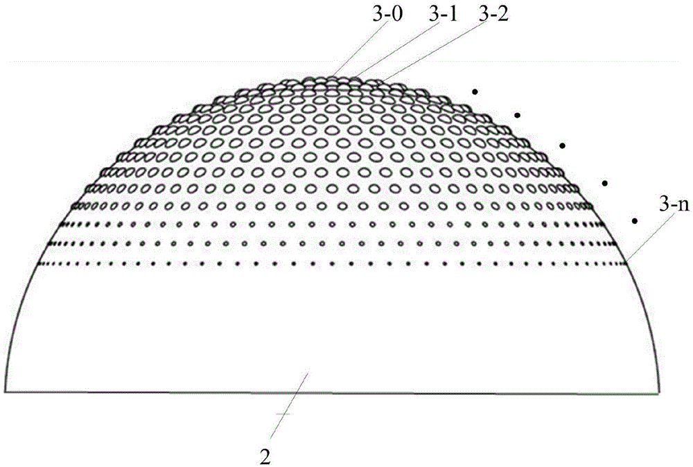
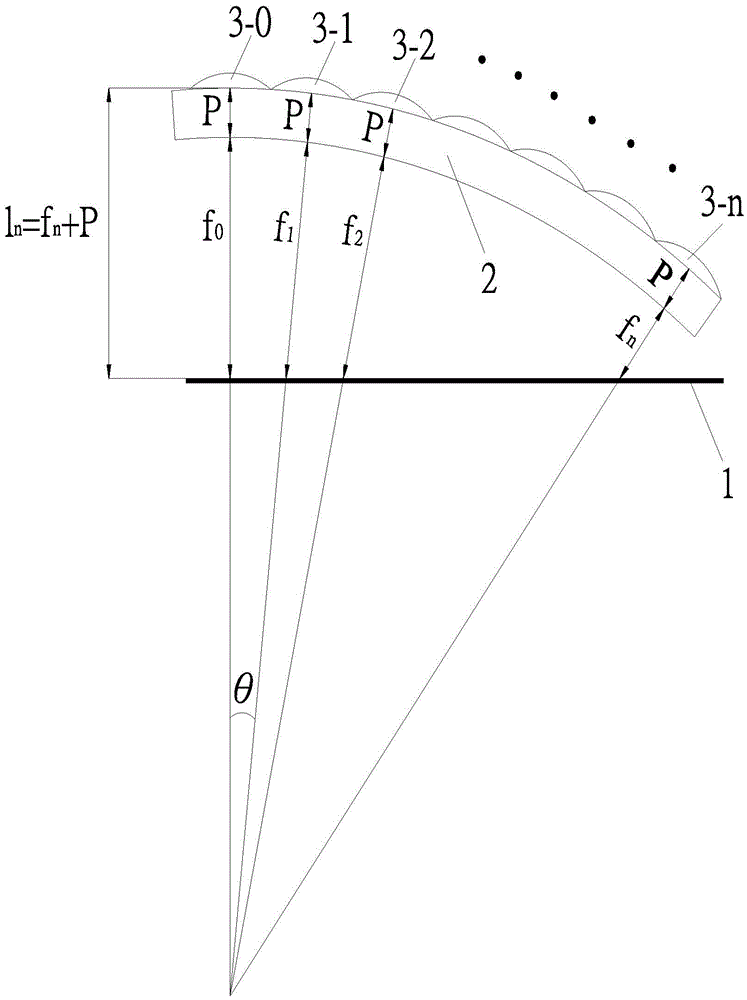
[0023] Such as Figure 1 to Figure 5 As shown, the curved surface bionic compound eye imaging device of the gradient focal length lens array of the present invention includes a photoelectric image sensor 1 , a glass spherical shell 2 , a lens array 3 , a mesh-shaped metal hole array 4 and a flat glass substrate 5 . The single-eye lens in the lens array 3 comprises n stages, and the single-eye lens positioned at the center of the array is counted as the 0-level single-eye lens 3-0, and the vertical distance from the center of the circular surface base of the single-eye lens to the photoelectric image sensor is counted as l 0 . The single-eye lens subsystems of other peripheral levels in the array are counted step by step as first-level single-eye lens 3-1, second-level single-eye lens 3-2...n-level single-eye lens 3-n, and the center of the circular base of e...


PUM


Abstract

The invention discloses a curved-surface bionic compound eye imaging device for a zoom lens array, and belongs to the field of lens bionic compound eye imaging devices according to a curved-surface array. The curved surface of a glass spherical shell of the device is provided with a lens array which consists of single eyes at a plurality of layers, wherein the curvatures and focal lengths of the single-eye lenses at all layers change layer by layer, but all the single-eye lenses are focused on the surface of a unique plane image sensor, thereby enabling the single-eye lens located at the edge of a view field to be able to be effectively focused, and avoiding a defocused state. According to the invention, a sieve-mesh-shaped metal hole array covers the surface of an image sensor, and each sieve mesh is enabled to be corresponding to one independent monocular lens optical path, thereby achieving an effect of segmenting the view field, achieving the integrated jointing of all monocular lens images, and preventing the interference and impact among the adjacent monocular lenses. The device is also high in resolution, is high in instantaneity, is easy to miniaturize, is easy to become light, and is convenient for manufacturing and maintenance.

Description

technical field [0001] The invention belongs to the field of bionic compound eye imaging device with curved surface array lens, and in particular relates to a curved surface bionic compound eye imaging device with progressive focal length lens array. Background technique [0002] Biological compound eyes are composed of a group of small monocular joints gathered together, and usually the entire compound eyes form a curved surface approximately spherical. Numerous independent imaging small monoculars can divide the entire field of view into several parts, and each independent small monocular corresponds to a relatively fixed field of view, and is only responsible for observing a small part of the image in the entire field of view. All images are spliced ​​to form a complete image. Because biological compound eyes usually have the advantages of small size, large field of view, and high sensitivity to moving objects, bionic compound eye devices based on multiple ommatidium arr...

Claims


Application Information

Patent Timeline
IPC IPC(8): G02B3/00G02B27/00
CPCG02B3/0087G02B3/0056G02B27/0075G02B27/0081
Inventor 王泰升李和福鱼卫星
Owner CHANGCHUN INST OF OPTICS FINE MECHANICS & PHYSICS CHINESE ACAD OF SCI
Learn More