Manufacturing method of color membrane substrate

A production method and technology for color filter substrates, which are applied in nonlinear optics, instruments, optics, etc., can solve the problems of product quality degradation, affecting the display effect of the picture, and impurity of the picture, saving process technology and materials, and improving product display. Quality, the effect of improving product perspective

Inactive Publication Date: 2016-04-06
WUHAN CHINA STAR OPTOELECTRONICS TECH CO LTD
View PDF5 Cites 30 Cited by
  • Summary
  • Abstract
  • Description
  • Claims
  • Application Information

AI Technical Summary

Problems solved by technology

[0005] Color filter substrate is an important part of liquid crystal display, such as Figure 1-2 As shown, the manufacturing process of the existing color filter substrate is as follows: on the substrate 100, a black matrix 200, a color photoresist layer 300, a flat layer or a common electrode layer 400, and a photoresist spacer 500 are sequentially fabricated; the current liquid crystal display device , when the human eye observes from different angles, the light emitted by the color photoresist layer 300 at the overlapping (Overlay) position of the adjacent color-resisting blocks 310, or at the position where the height of the adjacent color-resisting blocks 310 is uneven, will appear Overlapping will cause color mixing, resulting in impure picture and affecting the display effect of the picture
[0006] The current smart mobile and wearable devices such as mobile phones require higher precision in the color film, so the black matrix 200 and the color photoresist layer 300 will require thinner line widths. During the production process of the color photoresist layer 300, it is easier The superimposition of adjacent color-resisting blocks 310 causes color mixing, resulting in a decline in product quality

Method used


Image

  • Manufacturing method of color membrane substrate
  • Manufacturing method of color membrane substrate
  • Manufacturing method of color membrane substrate

Examples


no. 1 example

[0047] see image 3 , which is the first embodiment of the manufacturing method of the color filter substrate of the present invention, specifically includes the following steps:

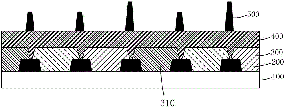
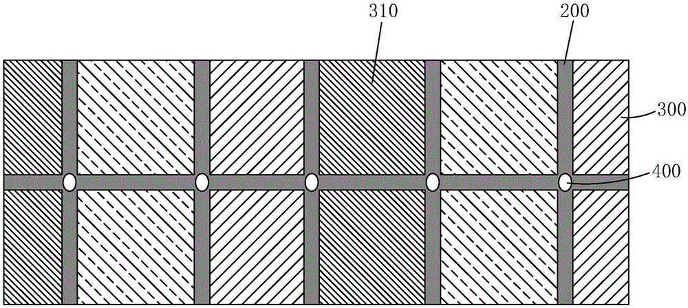
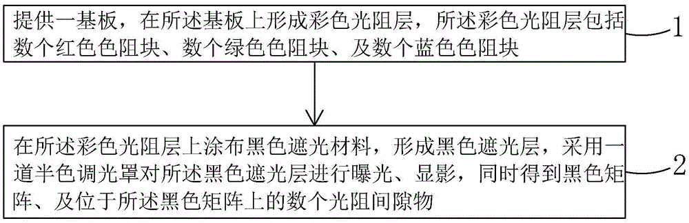
[0048] Step 1, such as Figure 4-5 As shown, a substrate 10 is provided, and a color photoresist layer 20 is formed on the substrate 10. The color photoresist layer 20 includes several red color resist blocks 21, several green color resist blocks 22, and several blue color resist blocks. Block 23.

[0049] Specifically, the substrate 10 is a transparent substrate, preferably a glass substrate.

[0050] Specifically, the color photoresist layer 20 may also include several white color resist blocks. Further, the manufacturing sequence of the red color-resisting block 21 , several green color-resisting blocks 22 , several blue color-resisting blocks 23 , and several white color-resisting blocks is not limited, and can be selected according to needs.

[0051] Step 2, such as Figure 6-8 As shown, a...

no. 2 example

[0056] see Figure 9 , which is the second embodiment of the manufacturing method of the color filter substrate of the present invention, specifically includes the following steps:

[0057] Step 1, such as Figure 10-11 As shown, a substrate 10 is provided, and a color photoresist layer 20 is formed on the substrate 10 using a halftone mask process, and the color photoresist layer 20 includes several red color resist blocks 21 and several green color resist blocks 22 , and several blue color resist blocks 23, while the color photoresist layer 20 has several transverse grooves 25 and several longitudinal grooves 26, and the several transverse grooves 25 and several longitudinal grooves 26 are located in phase The junction of adjacent color resistance blocks 21 / 22 / 23.

[0058] Specifically, the substrate 10 is a transparent substrate, preferably a glass substrate.

[0059] Specifically, the color photoresist layer 20 may also include several white color resist blocks. Furthe...

no. 3 example

[0066] see Figure 15 , which is the third embodiment of the manufacturing method of the color filter substrate of the present invention, specifically includes the following steps:

[0067] Step 1, such as Figure 16-17 As shown, a substrate 10 is provided, a first black matrix 70 is formed on the substrate 10, a color photoresist layer 20 is formed on the black matrix 20 and the substrate 10, and the color photoresist layer 20 includes several red color Resistance block 21 , several green color resistance blocks 22 , and several blue color resistance blocks 23 .

[0068] Specifically, the substrate 10 is a transparent substrate, preferably a glass substrate.

[0069] Specifically, the first black matrix 70 is arranged corresponding to the junction of the adjacent color resist blocks 21 / 22 / 23 on the color photoresist layer 20 .

[0070] Preferably, the color photoresist layer 20 may also include several white color resist blocks. Further, the manufacturing sequence of ...


PUM


Abstract

The invention provides a manufacturing method of a color membrane substrate. A halftone photomask is adopted for exposing and developing a black shading layer, and a black matrix and black photoresistance gap substances on the black matrix are manufactured at the same time, so that the problems such as color mixing and color differences generated when adjacent color blocking blocks on a color photoresistance layer are stacked or are not equal in height are effectively solved, and the angle of view of a product and the display quality of the product can be effectively improved; meanwhile, the manufacturing process can be shortened, materials can be saved, and the yield can be increased.

Description

technical field [0001] The invention relates to the field of display technology, in particular to a method for manufacturing a color filter substrate. Background technique [0002] With the development of display technology, liquid crystal displays (Liquid Crystal Display, LCD) and other flat display devices are widely used in mobile phones, TVs, personal digital assistants due to their advantages of high image quality, power saving, thin body and wide application range. , digital cameras, notebook computers, desktop computers and other consumer electronics products have become the mainstream of display devices. [0003] Most of the liquid crystal display devices currently on the market are backlight liquid crystal displays, which include a liquid crystal display panel and a backlight module. The working principle of the liquid crystal display panel is to place liquid crystal molecules between two parallel glass substrates. There are many vertical and horizontal small wires...

Claims


Application Information

Patent Timeline
Patent Type & Authority Applications(China)
IPC IPC(8): G02F1/1335
CPCG02F1/133514G02F1/133512G02F1/133516
Inventor 孙海燕
Owner WUHAN CHINA STAR OPTOELECTRONICS TECH CO LTD
Why Eureka
Try Eureka