
Notching machine for retaining rings

A cutting machine and buckle technology, applied in metal processing equipment, feeding devices, manufacturing tools, etc., can solve the problems of low work efficiency, high labor and time costs, time-consuming and other problems, and achieve a high degree of automation and production efficiency. The effect of saving manpower and time costs and avoiding the loss of raw materials

Inactive Publication Date: 2016-04-13
PINGHU PINYAO MACHINERY AUTOMATION CO LTD
View PDF7 Cites 7 Cited by
  • Summary
  • Abstract
  • Description
  • Claims
  • Application Information

AI Technical Summary

Problems solved by technology

[0002] The traditional oval buckle processing is to use the oval raw material with fracture ( Figure 10 ), the lengths of the two ends of the fracture of the raw material are different, and they are placed one by one by hand. The raw material has to be placed in a fixed angle direction. The long side and one effective section are processed into oval ring products with larger gaps ( Figure 11 ), the processing process requires the operator to be on the side of the cutting machine all the time, there are safety hazards in placing raw materials manually, such as the cutting machine may cut fingers, and the position of the manual insertion of the cut may not be standard, once the direction is placed Wrong, the incision will be cut on the shorter side of the end, so that the raw material will be wasted after the incision, and the required material, labor and time costs are relatively large; the processing and feeding speed of this method is slow, the efficiency is low, and it cannot be operated in batches processing, which is time-consuming and inefficient
Another mechanical transmission method is to directly set up a vertical channel through the bottom of the raw material warehouse. The raw material falls vertically. Under the action of gravity acceleration, the parts are easy to collide with the channel arm, the force on the bottom of the channel is concentrated, and the scattered parts cannot be ordered. Forward, this transmission method is not suitable for the buckle transmission of the punching machine

Method used


Image

  • Notching machine for retaining rings
  • Notching machine for retaining rings
  • Notching machine for retaining rings

Examples


Embodiment Construction

[0037] The present invention will be further described below in conjunction with the accompanying drawings to make the solution more clear.

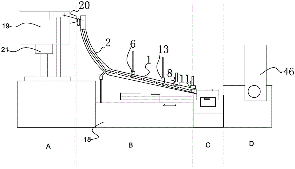
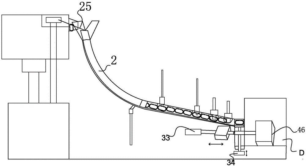
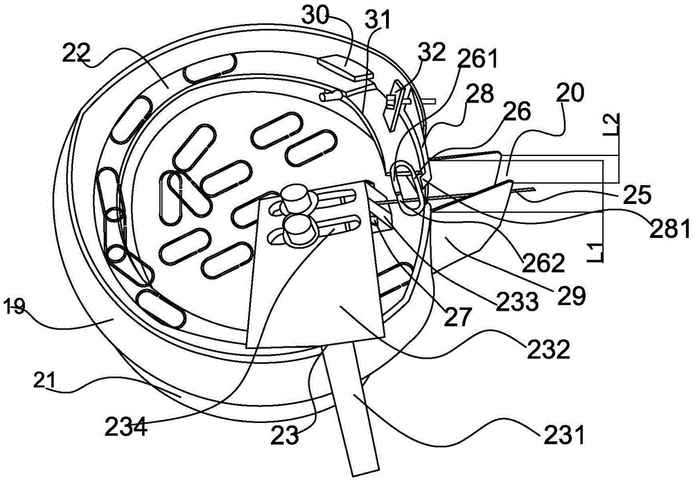
[0038] Such as figure 1 , figure 2 with Figure 4 As shown, the buckle slitting machine includes a feeding device A, a guide transmission device B, a feeding device C and a punch device D arranged on the frame 18 in sequence, and the feeding device includes a feeding bin 19, and the upper part of the feeding bin A discharge port 20 is provided, and the guide transmission device includes an inclined transmission channel 1, the highest end 1a of the transmission channel is connected to an arc-shaped guide plate 2, and a guide channel 3 is arranged in the guide plate, and the lowest end 2a of the guide channel is connected to the bottom of the transmission channel. The highest end 1a is connected. The middle part of the transmission channel 1 has a groove 4 for raw material transmission, and the upper part of the groove is covered with...


PUM


Abstract

A notching machine for retaining rings comprises a machine frame and is characterized by comprising a feeding device, a guiding and conveying device, a supplying device and a punch device, and the feeding device, the guiding and conveying device, the supplying device and the punch device are sequentially arranged on the machine frame; the feeding device comprises a feeding bin, and a discharging port is formed in the upper part of the feeding bin; the guiding and conveying device comprises an inclined conveying channel and an arc-shaped guiding plate bent downwards. According to the invention, automatic supply can be realized for machining of the retaining rings through motor vibration, raw material of the notching machine can be fed in an orientated mode and conveyed orderly, the angle of the raw material is fixed in the feeding process, and loss of the raw material caused by wrong manual supply directions is avoided; a connecting rod mechanism is adopted for driving an inclined cutter for cutting, stress on all the angles of the raw material is more balanced, the power needed for cutting is smaller, the automation degree and the production efficiency are higher, and the labor cost and the time cost are saved.

Description

technical field [0001] The invention relates to the field of buckle processing equipment, and mainly refers to a buckle cutting machine. Background technique [0002] The traditional oval buckle processing is to use the oval raw material with fracture ( Figure 10 ), the lengths of the two ends of the fracture of the raw material are different, and they are placed one by one by hand. The raw material has to be placed in a fixed angle direction. The long side and one effective section are processed into oval ring products with larger gaps ( Figure 11 ), the processing process requires the operator to be on the side of the cutting machine all the time, there are safety hazards in placing raw materials manually, such as the cutting machine may cut fingers, and the position of the manual insertion of the cut may not be standard, once the direction is placed Wrong, the incision will be cut on the shorter side of the end, so that the raw material will be wasted after the incisio...

Claims


Application Information

Patent Timeline
IPC IPC(8): B21D28/02B21D43/02
CPCB21D28/02B21D43/027
Inventor 黄春平
Owner PINGHU PINYAO MACHINERY AUTOMATION CO LTD
Features
  • Generate Ideas
  • Intellectual Property
  • Life Sciences
  • Materials
  • Tech Scout
  • Unparalleled Data Quality
  • Higher Quality Content
  • 60% Fewer Hallucinations
Learn More