Shock-absorbing metal pipe drilling device

A drilling device and metal pipe technology, applied in feeding devices, metal processing, boring/drilling, etc., can solve the problems of expensive purchase, failure to meet production standards, rough processing, etc.

Inactive Publication Date: 2016-04-13
SUZHOU YONGTONG STAINLESS STEEL CO LTD
View PDF8 Cites 10 Cited by
  • Summary
  • Abstract
  • Description
  • Claims
  • Application Information

AI Technical Summary

Problems solved by technology

[0002] At present, metal pipes are widely used in various industries such as petroleum, chemical, medical, food, light industry, mechanical instrumentation and other industrial pipelines and mechanical structural components, and become an indispensable material, including iron pipes, steel pipes , stainless steel tubes and aluminum tubes are widely used, so various processing equipment for metal tubes have emerged as the times require; usually, drilling metal tubes is a common processing method. However, the current drilling equipment is either too precise and expensive to purchase, which increases the processing cost, and the gain outweighs the gain; or it is too simple, the processing is too rough, and cannot meet the production standard, and some existing simple structures Because the equipment processes metal tubes one by one, the efficiency is not high, and some drilling equipment vibrates too much when drilling after the metal tube is placed, and the metal tube is easy to vibrate slightly left and right, which reduces the drilling accuracy and increases In addition, the metal tube is easy to fall off during the high-strength drilling process, which interrupts the processing and affects the work efficiency. It is difficult to meet the current production requirements.

Method used


Image

  • Shock-absorbing metal pipe drilling device
  • Shock-absorbing metal pipe drilling device

Examples


Embodiment Construction

[0013] Specific embodiments of the present invention will be further described in detail below.

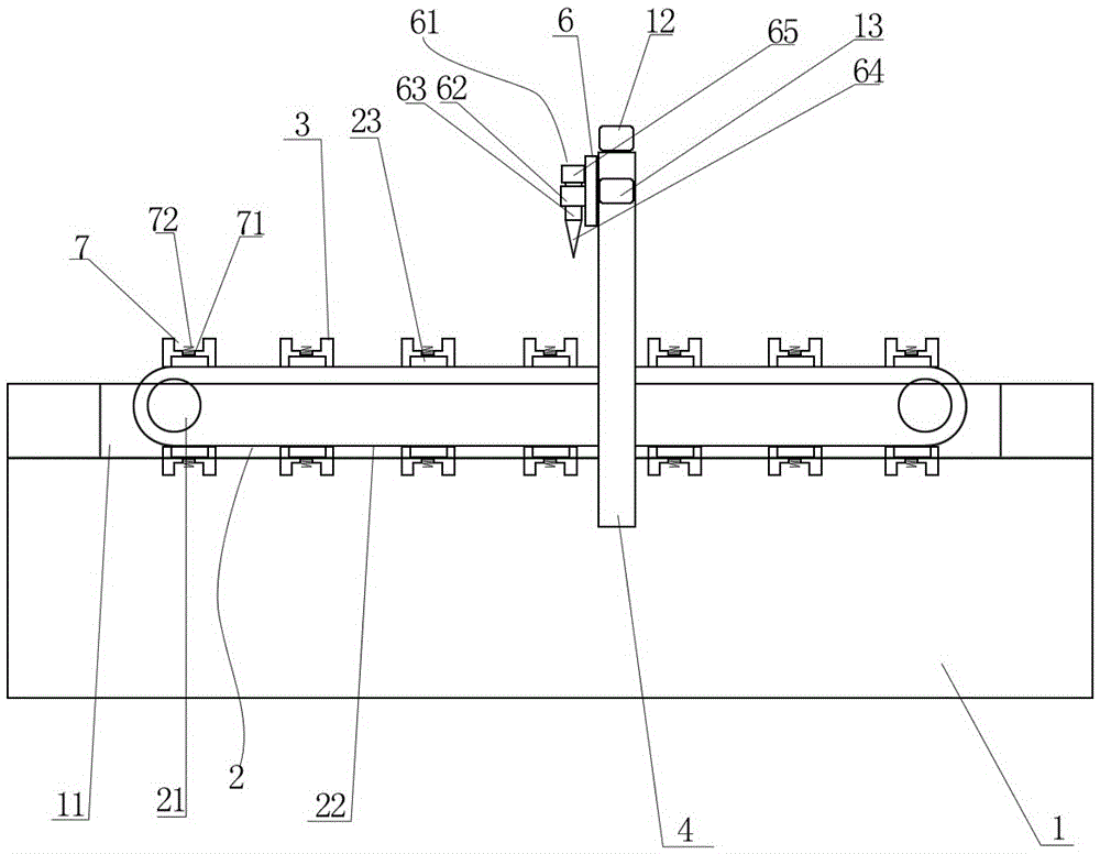
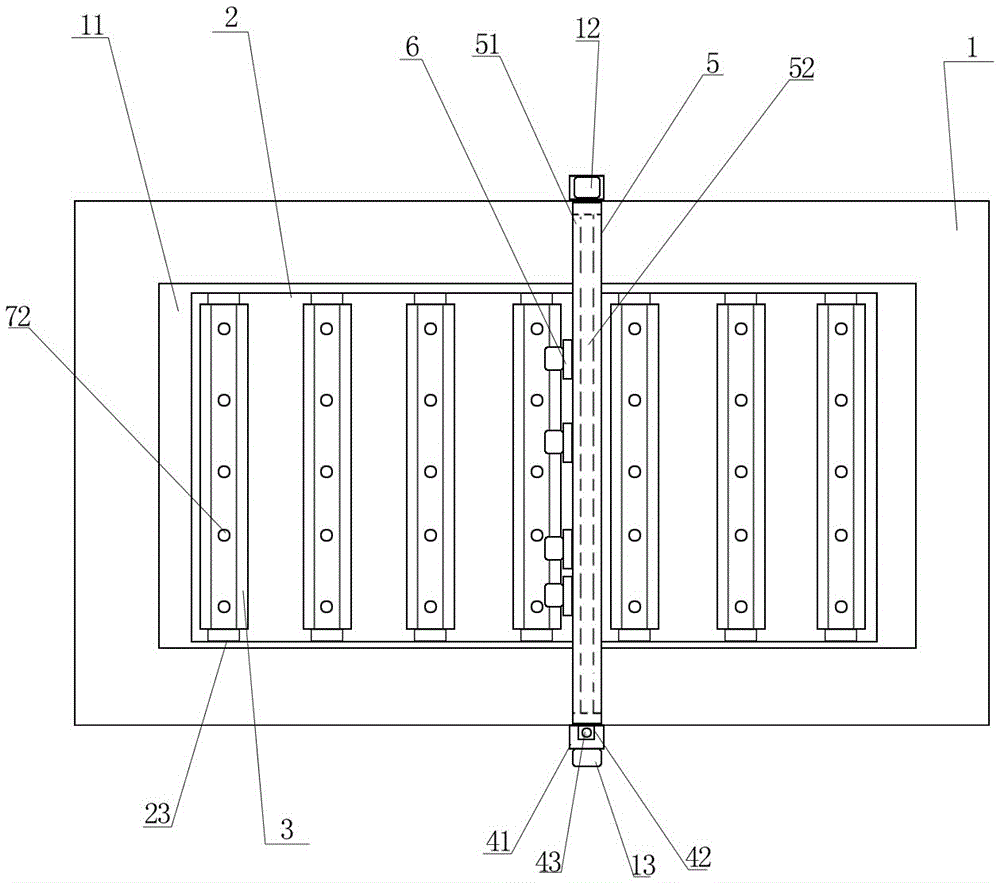
[0014] Such as figure 1 with figure 2 As shown, a shock-absorbing metal pipe drilling device 61 of the present invention includes a hollow frame 1, and is characterized in that: a groove 11 is provided on the top of the frame 1, and a rack transmission is horizontally arranged in the groove 11. Machine 2, the rack and rack conveyor 2 includes a rotating shaft 21 arranged on both sides of the frame 1 and a transmission belt 22 arranged on the rotating shaft 21. The two sides of the transmission belt 22 are correspondingly provided with a number of equidistant connectors 23, wherein two Connectors 23 across the conveyor belt 22 are connected with a metal pipe holder 3, the metal pipe holder 3 includes a strip groove 7 for placing the metal pipe to be processed, the bottom of the strip groove 7 is equidistantly provided with a number of circles Shaped concave hole 71, the correspo...


PUM


Abstract

The invention discloses a shock-absorbing metal pipe drilling device. The device comprises a hollow rack and is characterized in that a groove is formed in the top of the rack, a rack conveyor is horizontally arranged in the groove and comprises rotary shafts arranged on two sides of the rack and a conveying belt arranged on the rotary shafts, a plurality of connectors at equal intervals are correspondingly arranged at two side ends of the conveying belt, a metal pipe fixing base is connected between every two connectors and crosses over the conveying belt, a strip-shaped groove used for accommodating a to-be-machined metal pipe is formed in each metal pipe fixing base, a plurality of round holes are formed in the bottom of each strip-shaped groove at equal intervals, a high-pressure spring is correspondingly and perpendicularly arranged in each hole, a vertical spiral rod is perpendicularly arranged on each of two side surfaces of the rack, a transverse spiral rod is horizontally connected between the two vertical spiral rods, multiple fixing plates are perpendicularly arranged on the transverse spiral rod, and multiple drilling devices are arranged on the fixing plates. The shock-absorbing metal pipe drilling device has the advantages of convenience in use, high efficiency, high precision and the like.

Description

technical field [0001] The invention relates to a drilling device, in particular to a shock-absorbing metal pipe drilling device for drilling on the surface of a metal pipe. Background technique [0002] At present, metal pipes are widely used in various industries such as petroleum, chemical, medical, food, light industry, mechanical instrumentation and other industrial pipelines and mechanical structural components, and become an indispensable material, including iron pipes, steel pipes , stainless steel tubes and aluminum tubes are widely used, so various processing equipment for metal tubes have emerged as the times require; usually, drilling metal tubes is a common processing method. However, the current drilling equipment is either too precise and expensive to purchase, which increases the processing cost, and the gain outweighs the gain; or it is too simple, the processing is too rough, and cannot meet the production standard, and some existing simple structures Beca...

Claims


Application Information

Patent Timeline
Patent Type & Authority Applications(China)
IPC IPC(8): B23B39/16B23Q7/03B23Q5/40B23Q11/00B23B47/20
CPCB23B39/161B23B2215/72B23Q5/40B23Q7/003B23Q7/03B23Q11/0032
Inventor 龚伟峰
Owner SUZHOU YONGTONG STAINLESS STEEL CO LTD
Why Eureka
Try Eureka