
Automatic grinding device for die punch arc

A die punch and arc technology, which is applied in the field of die punch circular arc automatic grinding device, can solve the problems of grinding amount, arc shape grinding size, surface roughness concentricity cannot be guaranteed, and save money. , The effect of reducing the punching force and reducing the labor intensity

Inactive Publication Date: 2016-04-13
SHANDONG LIJIU SPECIAL PURPOSE ELECTROMOTOR CO LTD
View PDF0 Cites 6 Cited by
  • Summary
  • Abstract
  • Description
  • Claims
  • Application Information

AI Technical Summary

Problems solved by technology

This device solves the problem that the amount of grinding, arc shape, grinding size, surface roughness and concentricity cannot be guaranteed when grinding by hand.

Method used


Image

  • Automatic grinding device for die punch arc
  • Automatic grinding device for die punch arc

Examples


Embodiment Construction

[0010] The present invention will be further described below in conjunction with accompanying drawing:

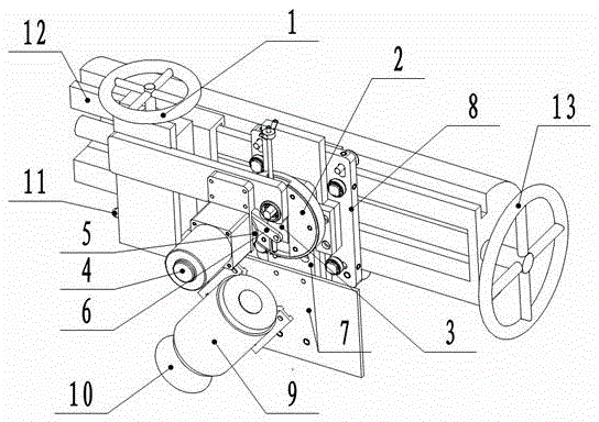
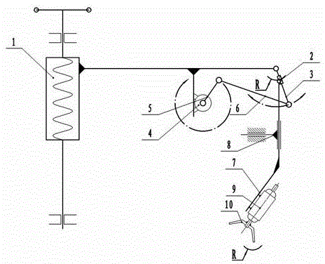
[0011] As shown in the figure, the present invention relates to an automatic grinding device for mold punch arcs, including a screw lifting pair, a radius adjustment disc, a swing rod, a drive motor, a drive rod a, a drive rod b, a grinding head motor mounting plate, Installation plate freedom limit mechanism, grinding head motor, bowl-shaped grinding wheel, horizontal slide rail seat locking handle, and horizontal slide rail are characterized in that: the whole device is installed on the horizontal slide rail 12, and the screw lifting pair 1 is installed on the column or the horizontal slide rail. On the rail 12, the horizontal slide rail 12 has a horizontal slide rail seat locking handle 11, the back of the mounting plate freedom restriction mechanism 8 is installed on the vertical lathe or the horizontal slide rail 12, and the grinding head motor mounting plate 7 is fixed...


PUM


Abstract

The invention discloses an automatic grinding device for a die punch arc. The automatic grinding device comprises a screw lifting pair, a radius adjusting disc, a swing rod, a drive motor, a drive rod a, a drive rod b, a grinding head motor installing plate, an installing plate freedom degree limiting mechanism, a grinding head motor and a bowl-shaped grinding wheel. The drive motor drives the swing rod to drive the radius adjusting disc to swing, and therefore the installing plate and the grinding head motor on the installing plate are driven to do same-radius arc track swinging. The device is low in cost, reasonable in structure, convenient to use, practical and suitable for grinding the punch die blanking force reduction arc.

Description

technical field [0001] The invention relates to the field of mechanical manufacturing, in particular to an automatic arc grinding device for die punches. Background technique [0002] Grinding the center position of the composite die punch with the punch in a circular or linear arrangement into one or several arcs to disperse the punching force is a widely used method to reduce the punching force and punching noise of the die. Methods. [0003] The punch of the mold must be ground after each use. Usually, the blade is ground on an ordinary grinding machine. The wear size is large and the frequency is high. Since the mold is made of high-strength materials, the material is expensive , The processing technology is complicated, and frequent grinding will cause a huge waste of materials. Now some people grind the middle part of the die punch into a concave arc shape, but manual grinding is used, and the arc is purely manually processed, and the grinding amount, shape, size, co...

Claims


Application Information

Patent Timeline
Patent Type & Authority Applications(China)
IPC IPC(8): B24B19/26B24B19/20B24B27/00B21D28/14
CPCB24B19/26B21D28/14B24B19/20B24B27/0092
Inventor 张成王毅
Owner SHANDONG LIJIU SPECIAL PURPOSE ELECTROMOTOR CO LTD
Learn More