
Structure for eliminating reservoir bottom geomembrane impervous blanket reverse seepage pressure and construction method

A technology of reverse osmosis and construction method, applied in infrastructure engineering, water conservancy engineering, marine engineering and other directions, can solve the problems of geomembrane safety operation threat, reverse seepage, high risk, etc., to achieve simple structure and reduce leakage The effect of low volume and low investment

Active Publication Date: 2016-04-13
POWERCHINA HUADONG ENG COPORATION LTD
View PDF5 Cites 1 Cited by
  • Summary
  • Abstract
  • Description
  • Claims
  • Application Information

AI Technical Summary

Problems solved by technology

When the above situation is encountered, if the water level drops suddenly and the continuous rainfall causes a large difference in the groundwater level of the surrounding reservoir bank relative to the reservoir water level, the geomembrane near the reservoir bank is also prone to reverse seepage caused by the reservoir bank groundwater, and local formation The jacking phenomenon poses a threat to the safe operation of the geomembrane
Especially when there is a fault connecting the bank of the reservoir with the bottom of the anti-seepage area, the risk is greater

Method used


Image

  • Structure for eliminating reservoir bottom geomembrane impervous blanket reverse seepage pressure and construction method
  • Structure for eliminating reservoir bottom geomembrane impervous blanket reverse seepage pressure and construction method
  • Structure for eliminating reservoir bottom geomembrane impervous blanket reverse seepage pressure and construction method

Examples


Embodiment Construction

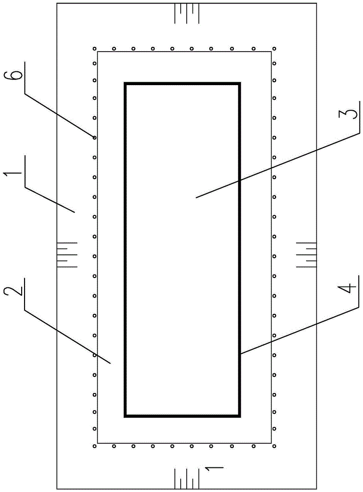
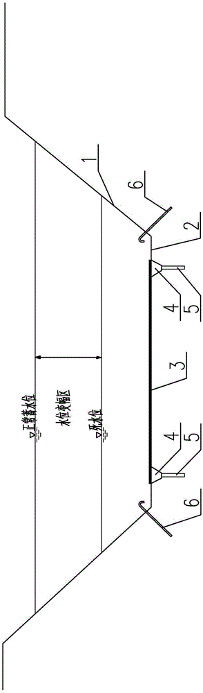
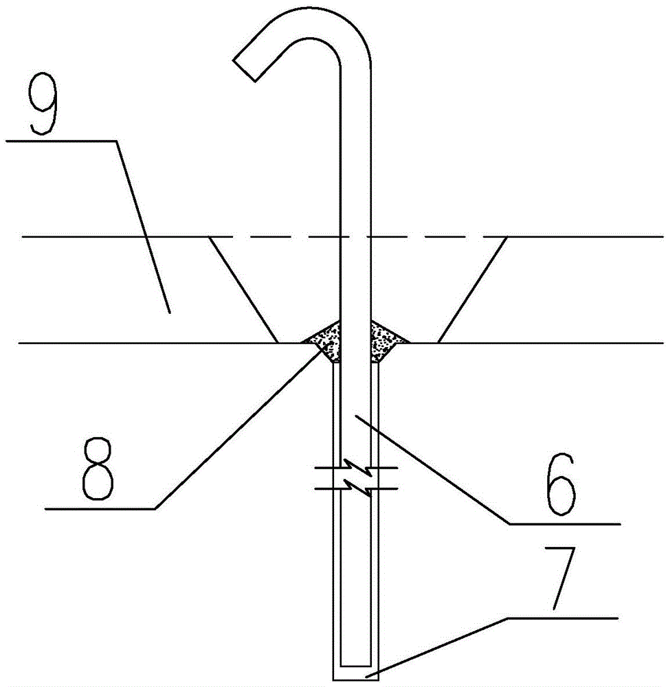
[0021] Such as figure 1 , figure 2 As shown, this embodiment is a structure and construction method for eliminating the reverse osmosis pressure of the geomembrane anti-seepage blanket at the bottom of the reservoir. It has a natural reservoir bank 1 with anti-seepage capability, a reservoir bottom 2 with leakage channels, and a reservoir bottom 2 The upper part is covered with a geomembrane anti-seepage layer 3; properly excavate and backfill the bottom 2 of the reservoir with leakage channels to form the lower support layer of the geomembrane anti-seepage layer, and connect the geomembrane anti-seepage layer 3 with the surrounding connection plate 4 (or tooth wall) is closed and connected, and the lower part of the peripheral connecting plate 4 is provided with curtain grouting 5 (or consolidation grouting), forming a relatively closed anti-seepage system on the periphery of the seepage channel at the bottom of the reservoir; at the same time, around the geomembrane anti-se...


PUM


Abstract

The invention relates to a structure for eliminating reservoir bottom geomembrane impervous blanket reverse seepage pressure and a construction method. The structure and the construction method aim at improving the geomembrane seepage control effect on the premise that no drainage channel under a geomembrane is additionally arranged, eliminating reverse seepage pressure caused by underground water of a reservoir bank and guaranteeing safe operation of a geomembrane. According to the technical scheme, the structure for eliminating the reservoir bottom geomembrane impervous blanket reverse seepage pressure comprises the natural reservoir bank with the seepage control capacity and a reservoir bottom with a leakage channel; the reservoir bottom is covered with a geomembrane seepage control layer, and the periphery of the geomembrane seepage control layer is provided with curtain grout or consolidation grout through a connecting plate or the tooth wall on the periphery; and meanwhile, drainage pipes are embedded into the mountain massif, close to one side of the reservoir bank, on the periphery of the geomembrane seepage control layer through drilling holes. The structure is suitable for the reservoir bottom immersed below the level of dead water; and the geomembrane is adopted for logical seepage control, and the structure is suitable for a seepage control project with the reverse seepage pressure existing on the reservoir bank and with an under-geomembrane drainage system unsuitable for arrangement and especially suitable for a reservoir basin of a pumped storage power station.

Description

technical field [0001] The invention relates to a structure and a construction method for eliminating the reverse osmosis pressure of a geomembrane anti-seepage blanket at the bottom of a reservoir. It is suitable for anti-seepage projects submerged in the bottom of the reservoir below the dead water level, using geomembrane for local seepage prevention, there is reverse seepage pressure on the reservoir bank and it is not suitable to set up a drainage system under the membrane, especially suitable for the reservoir basin of the pumped storage power station. Background technique [0002] When geomembrane anti-seepage is used as the main anti-seepage system at the bottom of the reservoir, the code stipulates that when there is reverse seepage pressure, a drainage system should be installed and drained out of the reservoir through the corridor. However, when the following conditions exist, it is not suitable to install a drainage system: geomembrane is used to treat the local ...

Claims


Application Information

Patent Timeline
IPC IPC(8): E02B3/16E02D19/16E02D19/20
CPCE02B3/16E02D19/16E02D19/20
Inventor 朱安龙张萍
Owner POWERCHINA HUADONG ENG COPORATION LTD
Features
  • Generate Ideas
  • Intellectual Property
  • Life Sciences
  • Materials
  • Tech Scout
  • Unparalleled Data Quality
  • Higher Quality Content
  • 60% Fewer Hallucinations
Learn More