Air inlet structure for dual-fuel engine

A dual-fuel engine, intake structure technology, applied in combustion engines, internal combustion piston engines, engine components, etc., can solve the problems of low natural gas replacement rate, short life of injection valves, waste of mixture, etc., and achieves compact structure and transformation. Small, improved combustion efficiency

Active Publication Date: 2016-04-13
NINGBO C S I POWER & MASCH GRP CO LTD
View PDF4 Cites 4 Cited by
  • Summary
  • Abstract
  • Description
  • Claims
  • Application Information

AI Technical Summary

Problems solved by technology

The way of pre-mixing before supercharging will make the intake pipe full of combustible mixture, which has great safety hazards and will also cause waste of mixture during scavenging; while the way of di

Method used


Image

  • Air inlet structure for dual-fuel engine
  • Air inlet structure for dual-fuel engine
  • Air inlet structure for dual-fuel engine

Examples


Embodiment Construction

[0023] The present invention will be further described in detail below in conjunction with the accompanying drawings and embodiments.

[0024] Such as Figure 1 to Figure 4 The example shown,

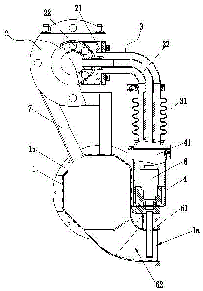
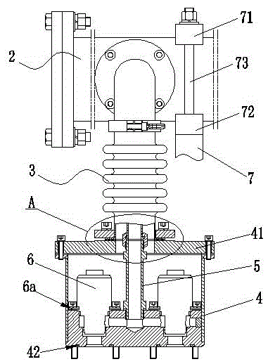
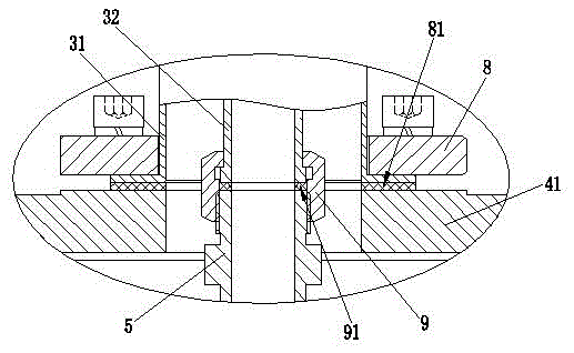
[0025] Explanation of icon numbers: air inlet pipe 1, air outlet 1a, inlet flange 1b, fuel inlet main pipe 2, outer air inlet main pipe 21, inner air inlet main pipe 22, fuel inlet branch pipe 3, outer air inlet branch pipe 31, inner inlet Gas branch pipe 32, valve box 4, cover plate 41, valve box bottom sealing ring 42, gas intake pipe 5, gas injection valve 6, gas injection valve fixing plate 6a, nozzle 61, injection hole 61a, partition plate 62, Support 7, upper pressing plate 71, lower pressing plate 72, stud 73, connecting flange 8, flange gasket 81, connecting nut 9, sealing washer 91.

[0026] Such as Figure 1 to Figure 4 as shown,

[0027] The intake structure of a dual-fuel engine of the present invention includes an air intake pipe 1 and a fuel intake main pipe 2, the fue...


PUM


Abstract

The invention discloses an air inlet structure for a dual-fuel engine. The air inlet structure comprises an air inlet pipe and a fuel air inlet manifold. The fuel air inlet manifold is connected with a valve piece box through a fuel air inlet branch pipe. The fuel air inlet manifold comprises an outer air inlet manifold body and an inner air inlet manifold body. The fuel air inlet branch pipe comprises an outer air inlet branch pipe body and an inner air inlet branch pipe body. One end of the outer air inlet branch pipe body is connected with the outer air inlet manifold body, and the other end of the outer air inlet branch pipe is connected with a cover plate of the valve piece box. One end of the inner air inlet branch pipe body is connected with the inner air inlet manifold body, and the other end of the inner air inlet branch pipe body is connected with a fuel gas inlet connecting pipe extending in the valve piece box. At least one fuel gas jetting valve communicated with the inner air inlet branch pipe body is arranged in the valve piece box, wherein a nozzle is arranged on the fuel gas jetting valve and extends in the air inlet pipe. The air inlet structure for the dual-fuel engine has the advantages of being simple and compact in structure, safe, reliable and high in combustion efficiency, and therefore the energy utilization rate is increased.

Description

technical field [0001] The invention relates to the technical field of energy saving and emission reduction of internal combustion engines, in particular to an intake structure of a dual-fuel engine. Background technique [0002] As the main prime mover, the internal combustion engine is widely used in human society. With the increasingly prominent problems of energy shortage and environmental pollution, countries are actively carrying out research on energy-saving and emission-reduction technologies for internal combustion engines. In the field of marine diesel engines, the research and application of dual-fuel and pure gas engine technology can effectively improve economy and reduce the emission of harmful substances such as NOx and particles. [0003] Diesel engines are widely used due to their wide power coverage and high thermal efficiency. However, due to the large amount of harmful emissions of exhaust gas from pure diesel engine fuel combustion, it is one of the imp...

Claims


Application Information

Patent Timeline
IPC IPC(8): F02B69/04F02M21/02
CPCF02B69/04F02B2201/064F02M21/0215F02M21/0218F02M21/023F02M21/0278Y02T10/30
Inventor 刘力军赵培秀王雷沈建华刘清明吴杰
Owner NINGBO C S I POWER & MASCH GRP CO LTD
Why Eureka
Try Eureka