Hydraulic diaphragm sealing system of hot air engine

A diaphragm sealing and hot air engine technology, which is applied in the direction of hot air variable capacity engine devices, mechanical equipment, machines/engines, etc., can solve problems such as reducing the time period of work, leaking gas, and restricting the development of hot air engines.

Active Publication Date: 2016-04-13
山东省阳信铭泰电气有限公司
View PDF4 Cites 3 Cited by
  • Summary
  • Abstract
  • Description
  • Claims
  • Application Information

AI Technical Summary

Problems solved by technology

[0002] The hot air engine seals the high-pressure working gas in a closed system and pushes the power piston to do work through thermal expansion and cold contraction. The power piston drives the output shaft to rotate through the connecting rod mechanism. External leakage of gas, when the amount of leaked gas is relatively large, causes a drop in efficiency and reduces the working time. Therefore, the sealing problem of the power piston and the gas distribution piston to the external environment has always restricted the development of the heat engine.

Method used


Image

  • Hydraulic diaphragm sealing system of hot air engine

Examples


Embodiment Construction

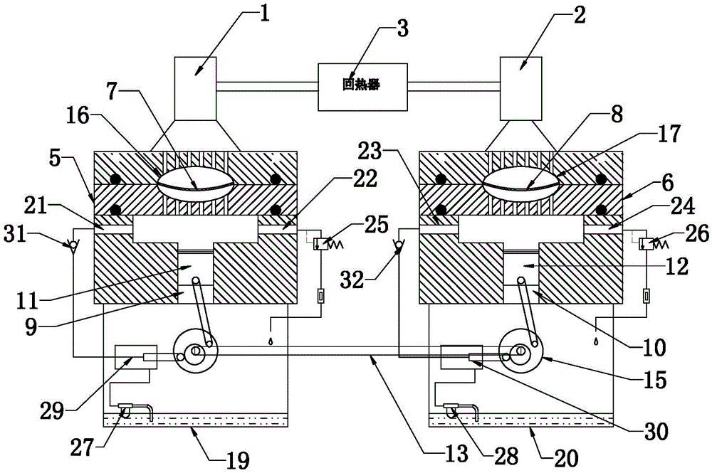
[0014] The hydraulic diaphragm sealing system for a hot air engine of the present invention will be further described in detail below in conjunction with the accompanying drawings and specific embodiments.

[0015] As shown in the figure, the hydraulic diaphragm sealing system for a hot gas engine of the present invention includes an expansion chamber 1 with a heating end, a compression chamber 2 with a cooling end, and a regenerator 3 connecting the expansion chamber and the compression chamber, canceling the original expansion chamber and The expansion piston and the compression piston in the compression chamber are connected to a No. 1 hydraulic chamber 5 at the power output port of the expansion chamber 1, and a No. 2 hydraulic chamber 6 is connected to the power output port of the compression chamber 2. The expansion chamber 1 is connected to the No. 1 hydraulic chamber. A No. 1 flexible diaphragm 7 is sealed between the chambers 5, and a No. 2 flexible diaphragm 8 is seal...


PUM


Abstract

The invention discloses a hydraulic diaphragm sealing system of a hot air engine. The hydraulic diaphragm sealing system of the hot air engine comprises a heating cavity, a cooling cavity and a heat regenerator connected between the heating cavity and the cooling cavity. Outlets of the heating cavity and the cooling cavity are each connected with a hydraulic cavity. Two flexible diaphragms are arranged between the heating cavity and the corresponding hydraulic cavity and between the cooling cavity and the corresponding hydraulic cavity respectively. The edges of the two flexible diaphragms are fixed to the corresponding hydraulic cavities respectively in a static sealing manner. The two hydraulic cavities are filled with hydraulic oil. The power output ends of the two hydraulic cavities are each provided with a cylinder body. Plungers are installed in the two cylinder bodies respectively. The power output ends of the two plungers drive the same rotary shaft to act. Two crank-link mechanisms have the phase difference adapting to the step sequence of the heating cavity and the cooling cavity. By the adoption of the structure, the requirement for no leakage in the working process is met, use efficiency is guaranteed, the service life of the system is prolonged, meanwhile flywheels can be driven by crank-links to operate to output power, and it is guaranteed that power is output reliably.

Description

technical field [0001] The invention relates to an improvement of a Stirling engine, in particular to a hydraulic diaphragm sealing system of a hot gas engine. Background technique [0002] The hot air engine seals the high-pressure working gas in a closed system and pushes the power piston to do work through thermal expansion and cold contraction. The power piston drives the output shaft to rotate through the connecting rod mechanism. Leaking gas outside, when the amount of gas leaking is relatively large, it will cause a decline in efficiency and reduce the working time. Therefore, the sealing problem of the power piston and the gas distribution piston to the external environment has always restricted the development of the heat engine. Contents of the invention [0003] The technical problem to be solved by the present invention is to provide a hydraulic diaphragm sealing system for a hot gas engine with good sealing effect, which can effectively reduce gas leakage and ...

Claims


Application Information

Patent Timeline
Patent Type & Authority Applications(China)
IPC IPC(8): F02G1/044F02G1/053
CPCF02G1/044F02G1/0535
Inventor 夏致俊
Owner 山东省阳信铭泰电气有限公司
Why Eureka
Try Eureka