Self-power-supply gas water heater controller

A technology for gas water heaters and controllers, which is applied to fluid heaters, lighting and heating equipment, etc. It can solve problems such as large limitations, achieve flexible use, strong penetrating power, and avoid the effects of electricity bills

Inactive Publication Date: 2016-04-13
SUZHOU CHUANGBICHENG ELECTRONICS TECH CO LTD
View PDF8 Cites 1 Cited by
  • Summary
  • Abstract
  • Description
  • Claims
  • Application Information

AI Technical Summary

Problems solved by technology

[0005]However, hydroelectric power generation devices or thermoelectric power generation have not been recognized by the majority of users, and have not even entered the market. For individual families, the cost of installing a self-powered device Both exceed the electricity bill generated by electricity, and it is troublesome, and it is not as direct as using electricity directly; for industrial production, directly adding this device in the production process will increase production costs, and this function cannot convince users to spend more Money to bear this part of the production cost, summed up as the function is too single, not attractive enough
[0006] However, with the progress of society, people are more and more pursuing efficient and convenient life. Generally, household appliances are equipped with corresponding remote controls to facilitate people's use. The existing gas Generally, water heaters must be placed where people can reach them so that people can control them, which has relatively large limitations. If the gas water heater can be equipped with a remote control, it will not only make the installation position of the gas water heater more flexible and reasonable, but also facilitate people to control it. , for this reason, it is necessary to produce a gas water heater controller that can cooperate with the remote control for wireless control and at the same time be self-powered

Method used


Image

  • Self-power-supply gas water heater controller
  • Self-power-supply gas water heater controller
  • Self-power-supply gas water heater controller

Examples


specific Embodiment

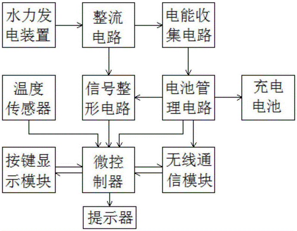
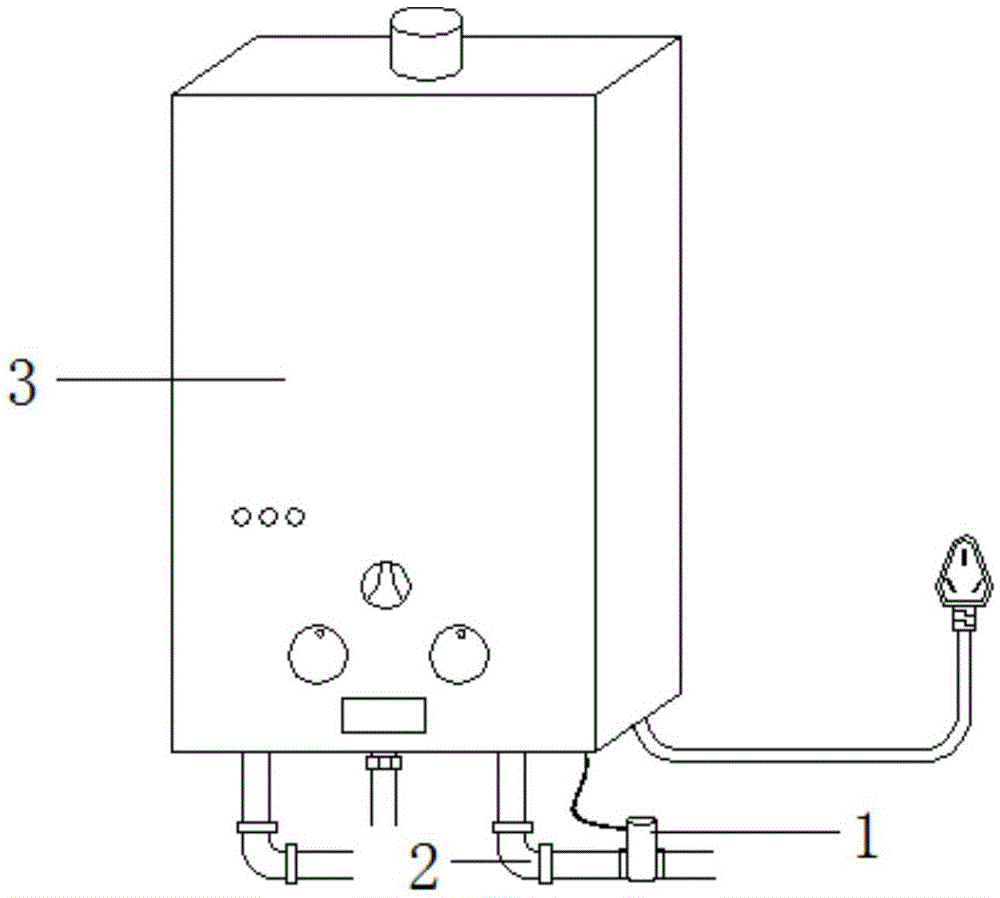
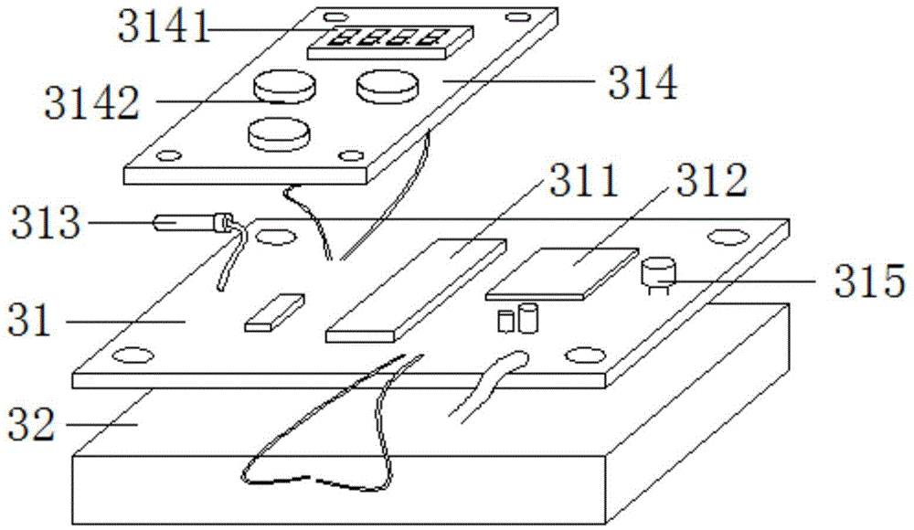
[0053] according to Figure 1-Figure 5 As shown, a self-powered gas water heater controller of the present invention is placed in the gas water heater body 3, the hydroelectric power generation device 1 is connected to the water pipe 2, connected to the water pipe 2 through the water inlet 151 and the water outlet 152, and Cooperate with the corresponding remote controller 4 to use, and its working process in combination with the water pipe 2 and the remote controller 4 is as follows:

[0054] 1) Self-powered: the water flow in the water pipe 2 pushes the water turbine 14 to rotate, drives the rotor 121 to rotate through the fixed shaft 13, and cuts the magnetic force lines with the stator 122 to generate alternating current;

[0055] 2) Electricity storage: the alternating current is transmitted to the electric energy collection circuit and the battery management circuit after being rectified, and finally transmitted to the rechargeable battery 32 to complete electric e...


PUM


Abstract

The invention discloses a self-power-supply gas water heater controller which comprises a hydroelectric generation device and an intelligent control board. The hydroelectric generation device is connected with a rechargeable battery. The rechargeable battery is connected with the intelligent control board. The intelligent control board comprises a microcontroller, a wireless communication module, a temperature sensor, a key display module and a prompter. By the adoption of the self-power-supply gas water heater controller, water flow energy is converted into electric energy through the hydroelectric generation device, the electric energy is stored in the rechargeable battery, and the self-power-supply and energy storage technical effects are achieved; water flow speed information is obtained through electric signals received by the microcontroller, water temperature information is obtained through the temperature sensor, wireless control is achieved through connection of a corresponding remote control unit and the wireless communication module, and therefore people uses a gas water heater more practically, conveniently, safely and reliably.

Description

technical field [0001] The invention relates to the field of gas water heater controllers, in particular to a self-powered gas water heater controller. Background technique [0002] Gas water heater, also known as gas water heater, refers to a water heater that uses gas as fuel and transfers high-temperature heat generated by gas combustion to cold water flowing through a heat exchanger to achieve the purpose of preparing hot water. Due to the actual situation and usage habits in our country, gas water heaters are still the first choice of many consumers. The advantages are high thermal efficiency, fast heating speed, stable temperature regulation, continuous use by multiple people, constant water temperature, and low purchase cost. [0003] Gas water heaters need electric energy to be used by the controller. The existing power supply methods generally use external power supply or battery power supply. The battery is a non-renewable energy source, and the battery needs to b...

Claims


Application Information

Patent Timeline
Patent Type & Authority Applications(China)
IPC IPC(8): F24H9/20
CPCF24H9/2035
Inventor 林振华伏小强
Owner SUZHOU CHUANGBICHENG ELECTRONICS TECH CO LTD
Why Eureka
Try Eureka