Micro-channel heat exchanger

A technology of micro-channel heat exchanger and heat exchange fins, applied in the field of heat exchange, can solve the problems of low heat exchange capacity of equipment, insufficient heat exchange of working medium, low heat absorption of working medium, etc., and achieve increased interaction. , good sealing, enhanced heat transfer effect

Inactive Publication Date: 2016-04-13
UNIV OF SHANGHAI FOR SCI & TECH
View PDF11 Cites 19 Cited by
  • Summary
  • Abstract
  • Description
  • Claims
  • Application Information

AI Technical Summary

Problems solved by technology

The design of this heat exchanger has the following disadvantages: 1. This heat exchanger only contains a single-layer microchannel and the channel is linear, and the working fluid stays in the channel for a short time. , its residence time in the tube will be shorter, the working fluid cannot fully exchange heat, and the heat exchange efficiency is not high; 2. The channels are separated from each other, and the fluids in different channels flow through the heat exchanger without any Mutual disturbance, single flow form, weak heat transfer capacity
[0005] The patent application number 201310217088.8 proposes a special

Method used


Image

  • Micro-channel heat exchanger
  • Micro-channel heat exchanger
  • Micro-channel heat exchanger

Examples


Embodiment Construction

[0034] The present invention will be further described below in conjunction with the embodiments shown in the accompanying drawings.

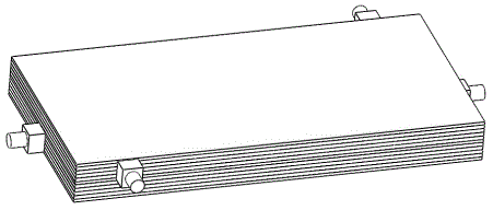
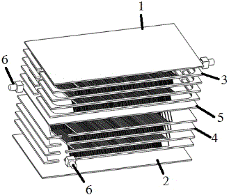
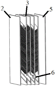
[0035] figure 1 It is a schematic diagram of the appearance structure of the present invention; figure 2 An exploded view of the heat sink in this example, represented by figure 2 It can be seen that the heat exchanger in this example includes an upper cover plate 1, a lower cover plate 2, a horizontal heat exchange fin unit, a longitudinal heat exchange unit, an intermediate partition plate 5, and a quality inlet / outlet unit 6, the upper cover plate 1, The middle partition 5 and the lower cover 2 are arranged parallel to each other in sequence, the transverse heat exchange fin unit is arranged between the upper cover 1 and the middle partition 5, and the longitudinal heat transfer fin unit is arranged between the middle partition 5 and the middle partition 5. Between the lower cover plate 2 ; the horizontal heat exchange fin unit and the l...


PUM


Abstract

A micro-channel heat exchanger comprises an upper cover plate, a lower cover plate, a transverse heat exchange structure, a longitudinal heat exchange structure, a middle partition plate and working medium inlet/outlet units. The upper cover plate, the middle partition plate and the lower cover plate are sequentially arranged in parallel, and a transverse heat exchange piece unit is arranged between the upper cover plate and the middle partition plate; a longitudinal heat exchange piece unit is arranged between the middle partition plate and the lower cover plate; and the transverse heat exchange piece unit and the longitudinal heat exchange piece unit are each provided with one inlet/outlet working medium unit; the transverse heat exchange structure at least comprises a transverse heat exchange unit, and the longitudinal heat exchange structure at least comprises a longitudinal heat exchange unit. The flow process of each flow way can be designed to be the same, and a diffusion fusion welding structure can be adopted for connection of partition plates. According to the heat exchanger, multilayer cross flow, uniform heat exchange and flow disturbance can be achieved, the heat exchange efficiency of the heat exchanger can be further improved, and the running cost is reduced.

Description

technical field [0001] The invention belongs to the technical field of heat exchange, and relates to a heat exchange device, especially a microchannel heat exchanger. Background technique [0002] With the rapid development of science and technology, whether it is in electronics or refrigeration equipment, the trend of high integration and high density has become more and more obvious, and the matching heat dissipation requirements are also getting higher and higher. Compared with traditional heat exchangers, microchannel heat exchangers have higher heat transfer efficiency and more economical working fluid consumption, and have gradually been widely researched and applied. [0003] Most of the current microchannel heat exchangers adopt a single-layer design, so that the flow form of the fluid in the microchannel is relatively simple, the time for flowing through the channel is relatively short, and the heat absorbed by the fluid per unit volume is not sufficient, resulting ...

Claims


Application Information

Patent Timeline
IPC IPC(8): F28D9/02F28F9/18
CPCF28D9/02F28F9/18
Inventor 崔晓钰朱悦邱子骞
Owner UNIV OF SHANGHAI FOR SCI & TECH
Why Eureka
Try Eureka