
Heat pipe flue gas waste heat recycling device and working medium

A flue gas waste heat recovery device technology, which is applied to indirect heat exchangers, lighting and heating equipment, etc., can solve the problems of poor heat transfer effect, and achieve the effects of easy replacement, quick disassembly, and superior heat transfer performance

Active Publication Date: 2016-04-13
TIANJIN JUNYITAI TECH DEV CO LTD
View PDF9 Cites 3 Cited by
  • Summary
  • Abstract
  • Description
  • Claims
  • Application Information

AI Technical Summary

Problems solved by technology

[0008] The method adopted in the above-mentioned patent documents has poor heat transfer effect and cannot fundamentally solve the problem of rapid heat transfer

Method used


Image

  • Heat pipe flue gas waste heat recycling device and working medium
  • Heat pipe flue gas waste heat recycling device and working medium
  • Heat pipe flue gas waste heat recycling device and working medium

Examples


Embodiment Construction

[0023] The present invention will be further described in detail below in conjunction with the accompanying drawings and through specific embodiments. The following embodiments are only descriptive, not restrictive, and cannot limit the protection scope of the present invention.

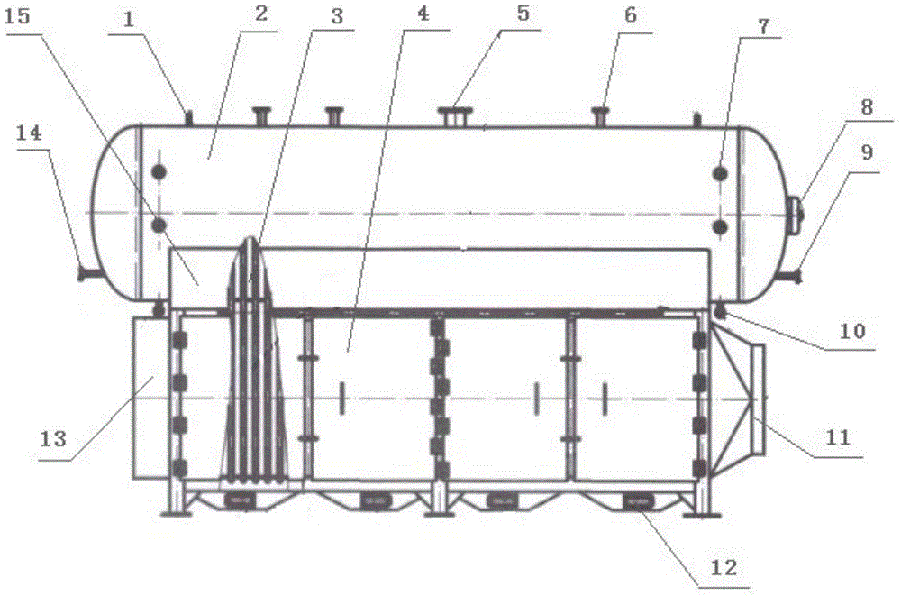
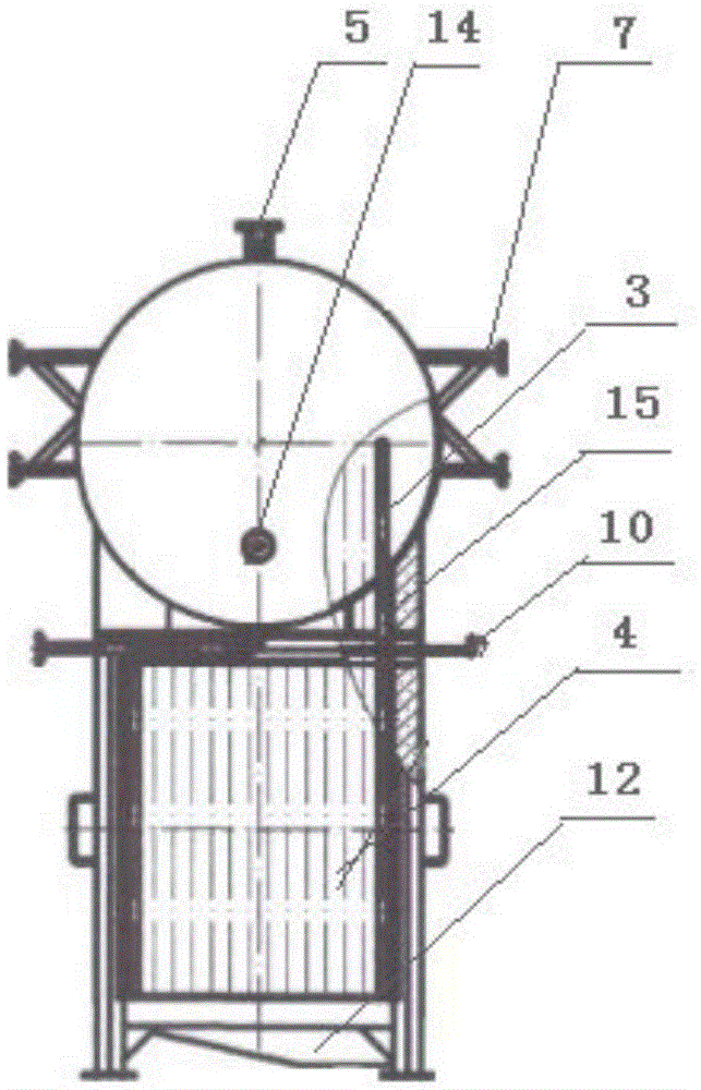
[0024] A heat pipe flue gas waste heat recovery device, comprising a steam generating tank 2, a heat pipe assembly 3, and a flue gas channel 4, the flue gas channel is a direction frame, one side is an air inlet 13, and the other side is an air outlet 11, and the The lower part of the flue gas channel is equipped with a plurality of ash removal ports 12 at intervals. A steam generating tank is installed on the upper part of the flue gas channel. The two sides of the steam generating tank are fixed on the upper part of the flue gas channel through connecting plates 15. The two ends of the heat pipe assembly are installed through the seal, the heat pipe evaporation section is in the flue gas channel, th...


PUM


Abstract

The invention relates to a heat pipe flue gas waste heat recycling device and a working medium. The heat pipe flue gas waste heat recycling device comprises a steam production tank, a heat pipe assembly and a flue gas channel, wherein the two ends of the heat pipe assembly are hermetically mounted between the flue gas channel and the steam production tank in a penetrating manner; a heat pipe evaporation section is in the flue gas channel; a heat pipe condensation section is in the steam production tank; and a heat exchange pipe is filled with the working medium. According to the heat pipe flue gas waste heat recycling device provided by the invention, the efficient heat pipe is adopted as a heat transfer element, high pressure steam is generated through absorbing flue gas waste heat with relatively high temperature, and high temperature hot water and heated air are used for production and life.

Description

technical field [0001] The invention belongs to the field of energy-saving equipment, in particular to a heat pipe flue gas waste heat recovery device and a working medium. Background technique [0002] Shell-and-tube heat exchangers are widely used in electric power, chemical industry and other industries, accounting for about 70% of the total heat exchangers; with the development of society, the consumption of energy and materials has increased sharply, and energy saving and consumption reduction have become important research and development in various industries Direction, and the increase in energy and material costs has made energy-efficient heat exchangers with high heat transfer efficiency and small size more important. [0003] The exhaust gas in the boiler carries a lot of heat, which is discharged into the atmosphere along with the exhaust gas. In recent years, more and more companies have seen these resources rich in exhaust gas, and people are trying to find way...

Claims


Application Information

Patent Timeline
Patent Type & Authority Applications(China)
IPC IPC(8): F28D15/02
CPCF28D15/02
Inventor 陈佳冬吕静远
Owner TIANJIN JUNYITAI TECH DEV CO LTD
Learn More