
Television imaging system modulation transfer function test device and method

A technology of modulation transfer function and imaging system, which is applied in the direction of measuring devices, optical instrument testing, and testing optical performance, etc., and can solve the problems of unstable intensity, affecting the gray distribution of CCD devices, and affecting MTF measurement results, etc.

Active Publication Date: 2016-04-13
西安应用光学研究所
View PDF5 Cites 15 Cited by
  • Summary
  • Abstract
  • Description
  • Claims
  • Application Information

AI Technical Summary

Problems solved by technology

[0006] In practice, due to the uneven spatial distribution of the intensity of the lighting source in the MTF test device of the TV imaging system, the intensity is not stable, and the characteristics of the TV imaging system itself, such as the receiver is a discrete device with different gray dynamic ranges, and the device has random Noise, etc., will affect the gray level distribution of the image surface image of the CCD device and the interpretation of the line spread function, etc., and ultimately affect the MTF measurement results

Method used


Image

  • Television imaging system modulation transfer function test device and method
  • Television imaging system modulation transfer function test device and method
  • Television imaging system modulation transfer function test device and method

Examples


Embodiment Construction

[0091] The present invention will be described below in conjunction with specific embodiments:

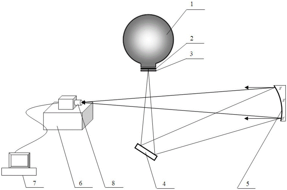
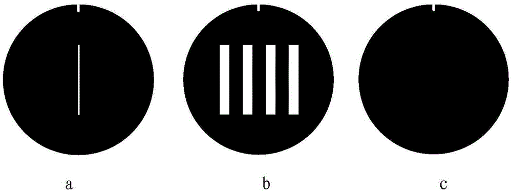
[0092] Such as figure 1 As shown, the TV imaging system modulation transfer function test device in this embodiment includes an integrating sphere light source system (1), a target group (2), a filter group (3), a plane mirror (4), and off-axis parabolic reflection Mirror (5) and computer processing system (7).

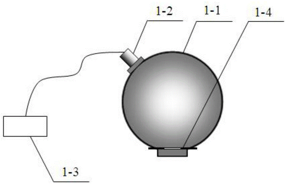
[0093] The integrating sphere light source system (1) is composed of an integrating sphere (1-1), a tungsten halogen lamp (1-2), a precision direct flow control power supply (1-3) and an electric variable diaphragm (1-4). In order to provide high time stability, high spatial uniformity and adjustable brightness of the illumination light, the computer processing system (7) controls the precision direct flow control power supply (1-3) and / or the motorized iris (1-4) to adjust the integral The spherical light source system (1) outputs light intensity. In this preferred embodime...


PUM

PropertyMeasurementUnit
Slit widthaaaaaaaaaa

Abstract

The invention provides a television imaging system modulation transfer function test device and method and belongs to the technical field of optical measurement. The television imaging system modulation transfer function test device and method are characterized in that a television imaging system to be tested is placed in an optical collimation system illuminated by an integrating sphere light source, of which the light intensity is adjustable and which is high in space uniformity, and slit targets are arranged in the focal plane of the optical collimation system; the slit targets, after passing through the optical collimation system and the television imaging system to be tested, are imaged to a target surface of the television imaging system; and after an image recording and processing system carries out a series of calculation and processing on the slit images, line spread function distribution of the slit targets and the MTF value are obtained, and thus MTF measurement of the television imaging system is finished.

Description

Technical field [0001] The invention relates to the field of optical metrology and measurement, in particular to a device and method for testing the modulation transfer function of a television imaging system. Background technique [0002] Modulation transfer function (MTF) is one of the most basic evaluation parameters of imaging system performance. It reflects the response characteristics of the imaging system to various spatial frequency components in the scene, and reflects the transmission ability of the imaging system to the target contrast of different spatial frequencies. Therefore, MTF It is an important index to evaluate the imaging performance of the imaging system. [0003] The visible light TV imaging observation system is responsible for searching, tracking and aiming the target. Its imaging performance is the key to determining the range and tracking accuracy of the system. Therefore, the imaging performance of the TV imaging system must be accurately measured and ev...

Claims


Application Information

Patent Timeline
IPC IPC(8): G01M11/02
CPCG01M11/0292
Inventor 王雷康登魁姜昌录杨斌马世帮杨红
Owner 西安应用光学研究所
Learn More