Method and optical sample cell for manufacturing a test block of a liquid insoluble particle detection device

A manufacturing method and technology of inspection blocks, applied in measuring devices, particle and sedimentation analysis, particle size analysis, etc., can solve problems such as damage, unstable slit size, and the size of inspection blocks cannot be too small

Inactive Publication Date: 2018-04-10
BEIJING LANKE IND & TRADE CO LTD
View PDF8 Cites 0 Cited by
  • Summary
  • Abstract
  • Description
  • Claims
  • Application Information

AI Technical Summary

Problems solved by technology

The problem in such a structure is that it is difficult to precisely control the width of the slit, because in this structure, the width of the slit is adjusted by the distance between the two stainless steel blocks. Will affect the distance between two stainless steel blocks, therefore, the size of the slit is very unstable
However, the development direction of liquid insoluble particle detection equipment is ultra-high pressure detection, especially the demand for online detection, and the detection of insoluble particles in liquid under ultra-high pressure has become the mainstream. Therefore, the liquid inlet pressure in the test block will rise to 200 to 300kg even higher, figure 2 At least six connecting threaded holes 31 for positioning the three-layer stainless steel plate on the test block in the test block, when subjected to ultra-high liquid pressure, the position of the threaded connection will become the weakest point of the strength of the entire test block, and the structural damage will also occur first At this position, therefore, the pressure of the test block is mainly restricted by the connecting threaded hole 31
[0009] (3) Since the connection threaded hole 31 needs to be provided, the size of the inspection block itself cannot be too small, otherwise it is difficult to meet the installation space requirements of the connection threaded hole 31, but the current development trend of inspection equipment is miniaturization, therefore, figure 2 Medium structure size will also restrict its further development

Method used


Image

  • Method and optical sample cell for manufacturing a test block of a liquid insoluble particle detection device
  • Method and optical sample cell for manufacturing a test block of a liquid insoluble particle detection device
  • Method and optical sample cell for manufacturing a test block of a liquid insoluble particle detection device

Examples


Embodiment 1

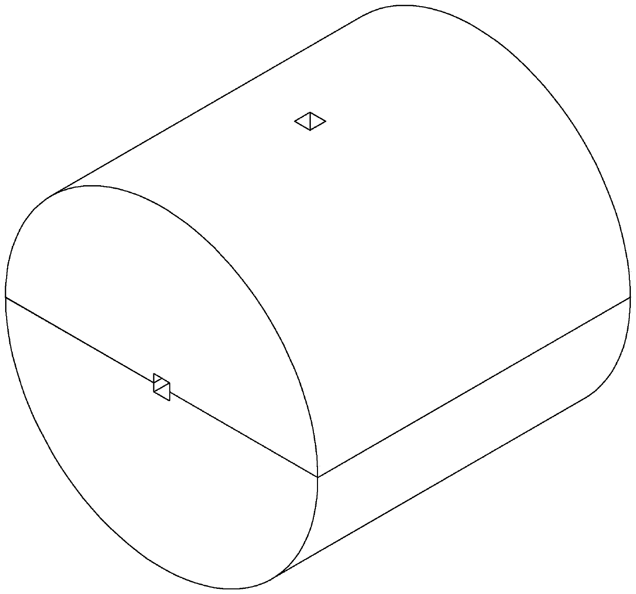
[0061] Process a stainless steel block whose external dimensions are suitable for liquid insoluble particle detection instruments with 316 stainless steel block, and process an embedded groove 63 according to the external dimensions of the test block in the center of this stainless steel block, its structure is as follows Figure 7 shown in . The test block is embedded in the embedded groove 63 and all the joints at the two ends of the connection block 6 are welded and sealed, so that the optical sample cell in this embodiment is formed, and its structure is as follows Figure 8 shown in .

Embodiment 2

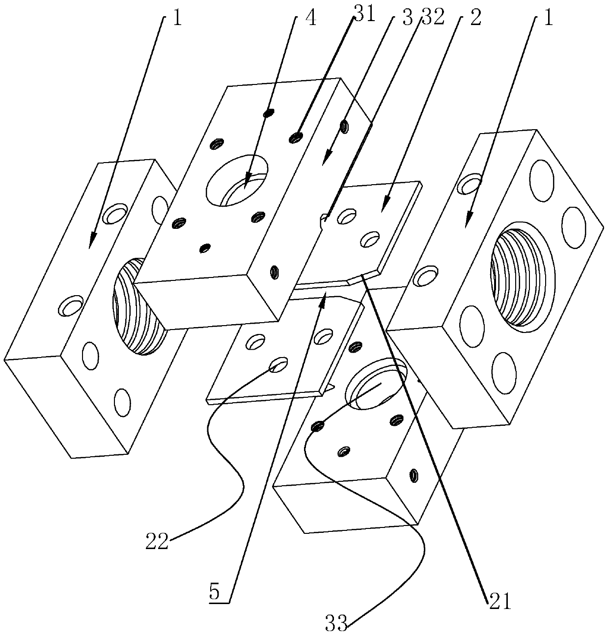
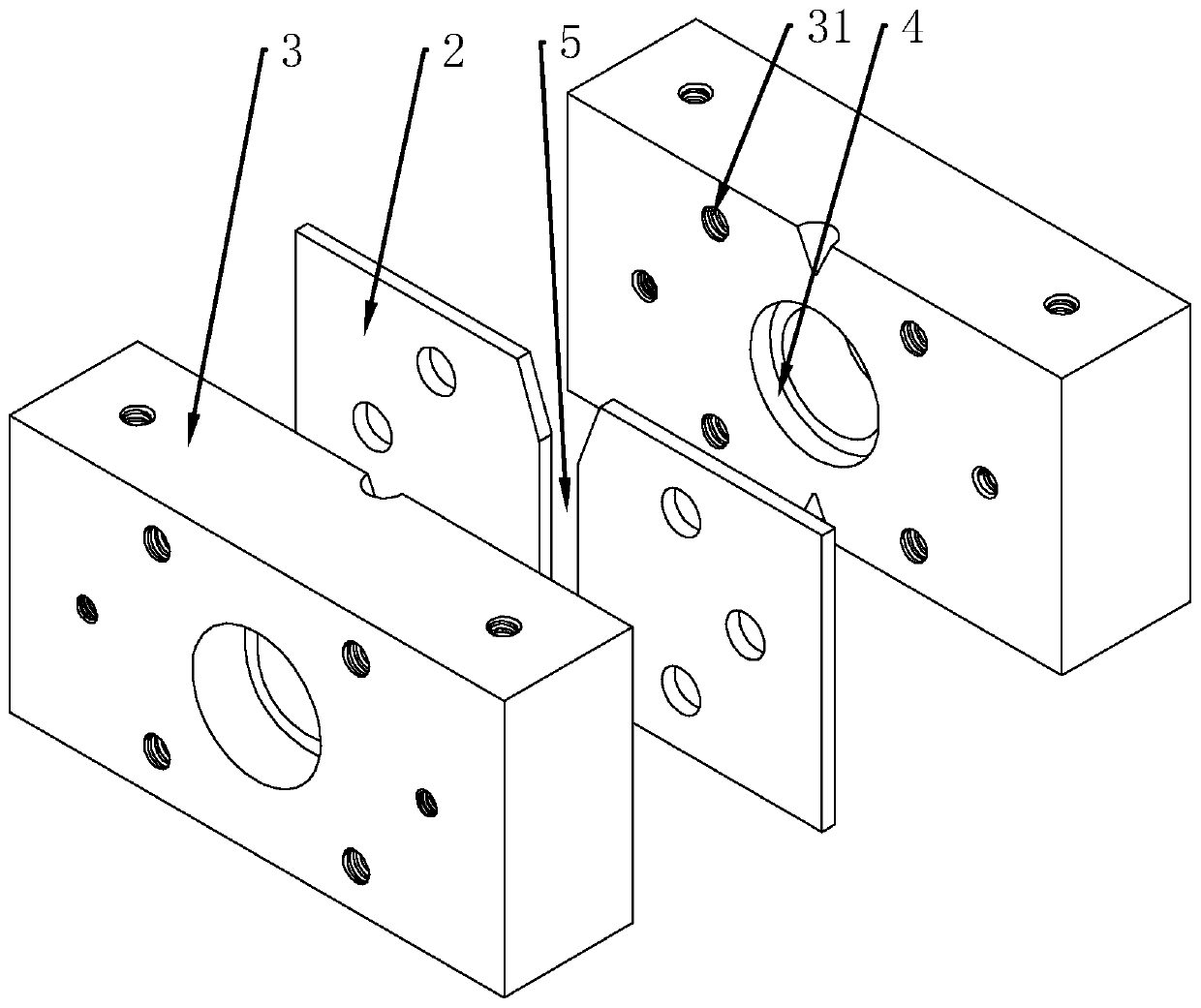
[0063] according to Figure 9 and Figure 10 The U-shaped block 65 and the cover plate 66 shown in the form are separately processed to connect the block 6, wherein the U-shaped groove inside the U-shaped block 65 is used to embed the inspection block. When using the split connection block 6 in this embodiment, the process of embedding the test block includes:

[0064] Step 1. Install the inspection block on the U-shaped block 65, and weld all the joints on three sides;

[0065] Step 2. Cover the cover plate 66 on the U-shaped block 65 , and weld around the joints between the U-shaped block 65 and the cover plate 66 .

[0066] The structure of the optical sample cell formed in embodiment 2 is as follows Figure 11 As shown, its airtightness is better than that of embodiment 1, and its reason is that when connecting block 6 in embodiment 1 is welded with inspection block, there are two vertical weld seams 7 less than embodiment 2, and these two passes weld When the manufact...


PUM


Abstract

The invention discloses a method for manufacturing a check block of an insoluble liquid particle detection device and an optical sample reservoir, aiming at solving the technical problem in the prior art that a stainless steel plate sealed in the manner of thread splicing and sealant is difficult to reach the pressure-bearing value for ultrahigh pressure detection is solved. According to the technical scheme, the check block in the optical sample reservoir is integrally welded in a special processing form and is wholly embedded into a connecting block, and then is welded again to form the optical sample reservoir for an insoluble liquid particle detector applied to an optical resisting method. The optical sample reservoir with the check block in such arrangement has the highest loading capacity reaching above 400kg and can fully meet the requirement for ultrahigh pressure detection.

Description

technical field [0001] The invention relates to a detection device for liquid insoluble particles, more specifically, it relates to a detection technology applied to the measurement of insoluble particles by photoresistance method and a test block and a sample pool in the particle size detection device. Background technique [0002] With the increasing progress and high-speed development of science and technology and modern industry, there are higher and higher requirements for the purity of working media or products used in many industries and the corresponding detection and monitoring technology. Among them, the needs of industries such as microelectronics, medicine, oil exploration, lubricating oil for high-speed machinery, and hydraulic (pneumatic) transmission are particularly prominent. Among the liquid insoluble particle detection equipment, several common detection instruments include optical particle counter, Coulter counter and condensation nuclei counter, among wh...

Claims


Application Information

Patent Timeline
Patent Type & Authority Patents(China)
IPC IPC(8): G01N15/02
CPCG01N15/0205
Inventor 不公告发明人
Owner BEIJING LANKE IND & TRADE CO LTD
Why Eureka
Try Eureka