High-voltage shunt circuit for ignition system

A technology of ignition system and shunt circuit, which is applied in the direction of control/regulating system, electrical components, adjusting electrical variables, etc., to achieve the effect of increasing ignition energy, improving combustion efficiency, and prolonging discharge time

Active Publication Date: 2016-04-13
UNITED AUTOMOTIVE ELECTRONICS SYST
View PDF4 Cites 5 Cited by
  • Summary
  • Abstract
  • Description
  • Claims
  • Application Information

AI Technical Summary

Problems solved by technology

However, the voltage of high-voltage energy storage devices can usually reach thousands of volts, which has greatly exceeded the maximum withstand voltage of a single electronic switch at present, so there is a problem of voltage division

Method used


Image

  • High-voltage shunt circuit for ignition system
  • High-voltage shunt circuit for ignition system
  • High-voltage shunt circuit for ignition system

Examples


Embodiment Construction

[0016] The present invention will be further described in detail below in conjunction with the accompanying drawings and specific embodiments.

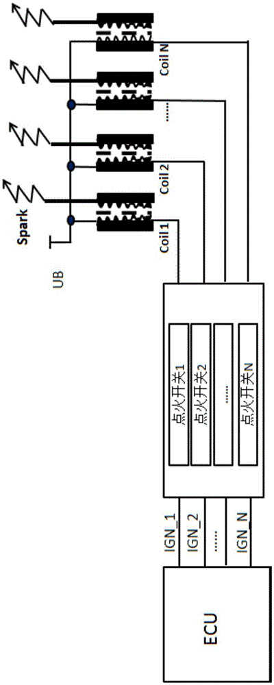
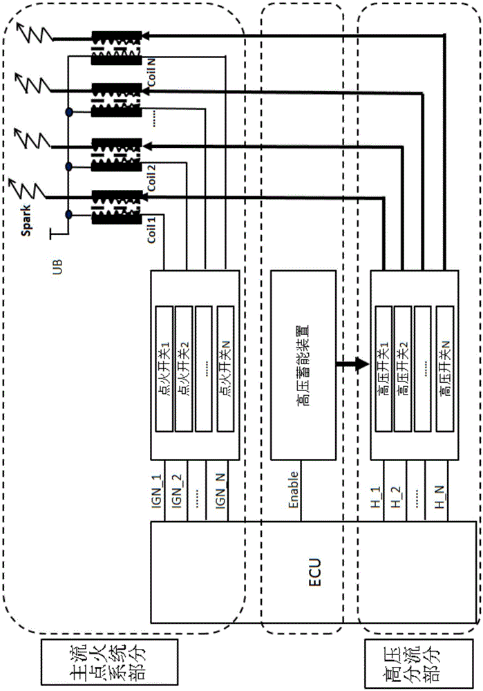
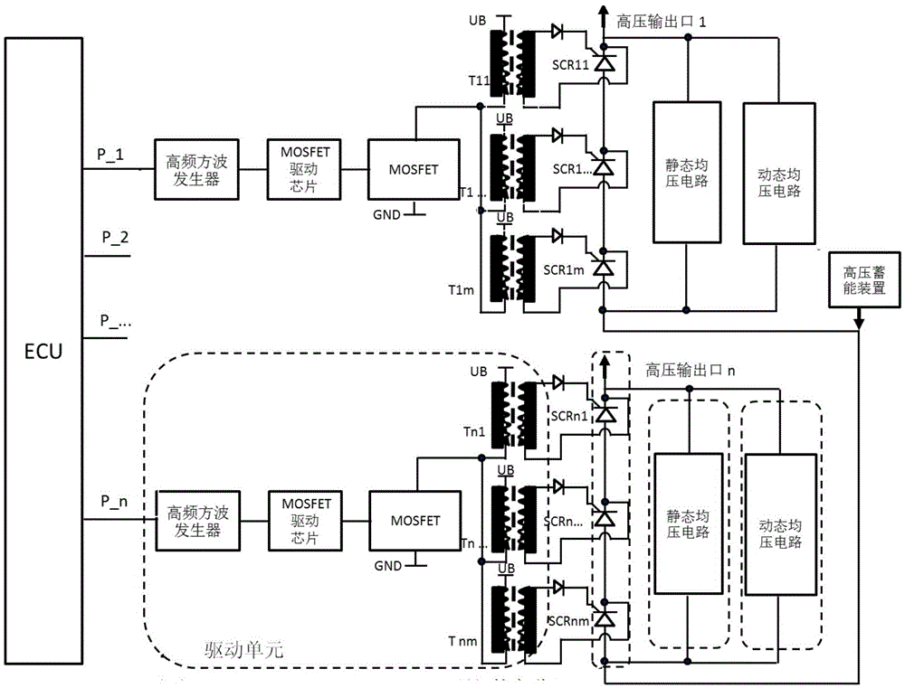
[0017] The high-voltage shunt circuit for ignition system of the present invention is suitable for ignition systems with high-voltage energy storage devices, such as figure 2 As shown, a high-voltage energy storage device is connected to the secondary coil of the corresponding ignition coil through several high-voltage switches, and the ECU controls the opening of the high-voltage switch of the corresponding ignition coil, so that the high-voltage energy storage device can continue to flow for the secondary coil in turn. Since all ignition coils share a high-voltage energy storage device, which can generate thousands of volts of high voltage, each ignition coil is equipped with a high-voltage shunt circuit, which is equivalent to a high-voltage switch, such as image 3 As mentioned above, it includes a drive unit and some thyristors,...


PUM


Abstract

The invention discloses a high-voltage shunt circuit for an ignition system. The high-voltage shunt circuit comprises a drive unit and a plurality of thyristors, wherein the drive unit comprises a square-wave generator, an MOSFET drive chip, an MOSFET and a plurality of rectifier circuits; an input end of the square-wave generator is electrically connected with an ECU; an output end of the square-wave generator is electrically connected with the input end of the MOSFET drive chip; the MOSFET is connected with the MOSFET drive chip and the rectifier circuits respectively; each thyristor corresponds to one rectifier circuit; all thyristors are sequentially connected with one another in series; input ends of the thyristors are connected with a high-voltage energy storage device; and output ends are connected with a secondary coil of an ignition coil in the ignition system. The plurality of thyristors are connected in series to form the high-voltage shunt circuit with a higher withstand voltage, so that the problem of high-voltage shunting of a high-energy ignition system with the high-voltage energy storage device can be solved.

Description

technical field [0001] The invention relates to the ignition system of an engine, and specifically belongs to a high-voltage shunt circuit used for series connection of thyristors in the ignition system. Background technique [0002] The ignition system of the engine mainly includes an electronic control unit (Electronic Control Unit, referred to as ECU), sensors related to the ignition system, an ignition switch, an ignition coil, and a spark plug. The ignition coil is the core component of the engine ignition system, such as figure 1 As shown, the main structure includes a primary coil, a secondary coil, and a magnetically permeable iron core. [0003] At present, the working mode of the mainstream engine ignition system is as follows: figure 1 As shown, the ignition switch is controlled by the engine ECU. When charging, the ECU receives the signal for processing and outputs a control signal to turn on the ignition switch, the primary coil starts charging, and the energy...

Claims


Application Information

Patent Timeline
Patent Type & Authority Applications(China)
IPC IPC(8): H02M3/135F02P3/04F02P3/05
CPCF02P3/04F02P3/05H02M3/135
Inventor 何宏宇程捷孙晓庆卢学文王玉军
Owner UNITED AUTOMOTIVE ELECTRONICS SYST
Why Eureka
Try Eureka