Eureka AIR delivers breakthrough ideas for toughest innovation challenges, trusted by R&D personnel around the world.

Rigid-flex board with different flexible appearances and preparation method of rigid-flex board

A rigid-flex board and shape technology, applied in multilayer circuit manufacturing, printed circuit manufacturing, conductive pattern layout details, etc., can solve the problems of unable to meet the installation requirements of flexible areas, too thick flexible areas of branch lines, and the area occupied by flexible areas. , to achieve the effect of saving multi-branch current wiring space, improving randomness, and satisfying bending performance

Active Publication Date: 2016-04-13
GUANGZHOU FASTPRINT CIRCUIT TECH +2
View PDF6 Cites 9 Cited by
  • Summary
  • Abstract
  • Description
  • Claims
  • Application Information

AI Technical Summary

Problems solved by technology

[0003] The existing technology is to arrange the flexible lines of each branch side by side on a flexible core board when they are parallel; or to arrange them in layers on a multi-layer flexible core board. Both methods have great limitations:
[0004] (1) In the case of single-layer wiring, the flexible area where each branch converges will occupy a large area, which greatly wastes the wiring space
[0005] (2) In multi-layer wiring, the flexible part of the branch is only wired on one of the core boards, and for the convenience of production, the unwired flexible core board will also be pressed together with the branch to the rigid area, resulting in too thick a flexible area of ​​the branch line , which seriously affects the bending performance
[0006] (3) Single-layer wiring and multi-layer wiring have the same shape in the branch line convergence area, which cannot meet the installation requirements of the limited width of the flexible area

Method used


Image

  • Rigid-flex board with different flexible appearances and preparation method of rigid-flex board
  • Rigid-flex board with different flexible appearances and preparation method of rigid-flex board
  • Rigid-flex board with different flexible appearances and preparation method of rigid-flex board

Examples


Embodiment Construction

[0036] The present application will be further elaborated below by way of examples.

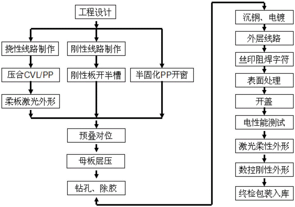
[0037] A kind of preparation method of the rigid-flex board with different flexible shapes in this embodiment (flow chart is as follows figure 2 shown), including the following steps:

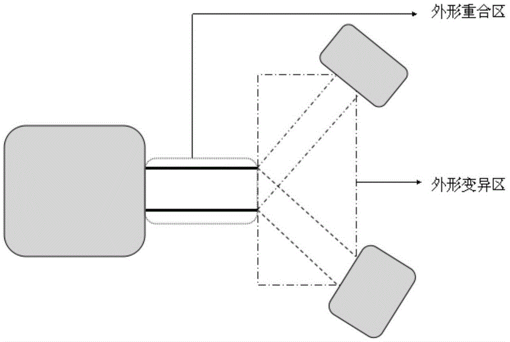
[0038] (1) Make at least two flexible core boards, make circuit patterns on the surface of each flexible core board according to conventional methods, and then perform laser shape operations (such as image 3 shown);

[0039] The flexible core board is provided with a shape overlapping area and a shape variation area, and the area of ​​the laser shape operation is the shape variation area; the shape line of the laser shape operation extends to more than 0.15mm in the shape overlap area;

[0040] This operation can ensure that the flexible shape variation area will not be damaged. If it is a one-time molding, this area is easily damaged by a laser or a milling machine; and the outline line of the laser shape...


PUM


Abstract

The invention relates to a rigid-flex board with different flexible appearances and a preparation method of the rigid-flex board. The preparation method comprises the following steps: fabricating flexible core boards, rigid core boards and prepregs; stacking all flexible core boards and rigid core boards in a set order; carrying out laminating, drilling, degumming, copper deposition, electroplating, outer line fabrication, screen-printing and resistance welding procedures; conventionally carrying out surface treatment; carrying out uncapping operation on a circuit board which is subjected to surface treatment and exposing a flexible region; and carrying out laser appearance operation on the uncapped circuit board, so as to obtain the rigid-flex board with different flexible appearances. According to the method, appearance treatment is carried out on a flexible substrate overlapping region before lamination, so that the randomness in a hierarchical structure design on the rigid-flex board can be improved; multi-branch interconnection requirements are met; multi-branch current wiring space can also be saved; the bending performance of branch circuits is met; and the space of the printed board is saved.

Description

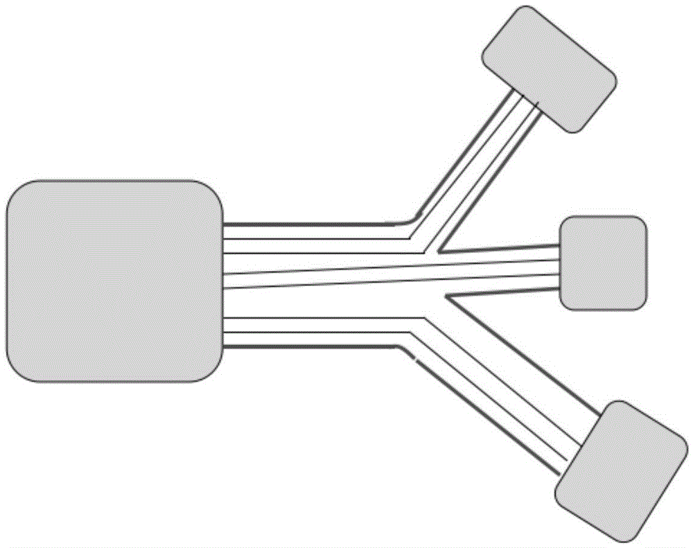
technical field [0001] The invention relates to the field of printed circuit board manufacturing, in particular to a rigid-flex board with different flexible shapes and a preparation method thereof. Background technique [0002] With the continuous development of electronic products in the direction of multi-functionality, miniaturization, light weight and high performance, the requirements for miniaturization and high density of printed circuit boards are also increasing, and its products are also changing from traditional printed circuit boards to high-density Build-up printed board development. For rigid-flex boards, the rigid main board connects multiple branch rigid boards through the flexible area is also a direction of high-density development, such as figure 1 shown. [0003] The existing technology is to arrange the flexible lines of each branch side by side on a flexible core board when they are parallel; or to arrange them in layers on a multi-layer flexible cor...

Claims


Application Information

Patent Timeline
IPC IPC(8): H05K3/46H05K1/02
CPCH05K1/02H05K3/46H05K3/4632H05K1/0298H05K2203/06
Inventor 徐波莫欣满陈蓓
Owner GUANGZHOU FASTPRINT CIRCUIT TECH
Why Eureka
Eureka Blog
Learn More