
Machine design comprising a pivotable tool spindle

A technology for processing machine tools and spindles, which is applied in the direction of metal processing machinery parts, machine tool parts, metal processing equipment, etc., can solve the problems of structure cost and cost, and achieve the effect of high processing precision

Inactive Publication Date: 2016-04-13
GROB WERKE & K G
View PDF6 Cites 5 Cited by
  • Summary
  • Abstract
  • Description
  • Claims
  • Application Information

AI Technical Summary

Problems solved by technology

This leads to considerable structural outlay, especially in the case of large and heavy workpieces
The considerable weight of the workpiece must be taken into account when designing the axis of rotation, which leads to corresponding costs

Method used


Image

  • Machine design comprising a pivotable tool spindle
  • Machine design comprising a pivotable tool spindle
  • Machine design comprising a pivotable tool spindle

Examples


Embodiment Construction

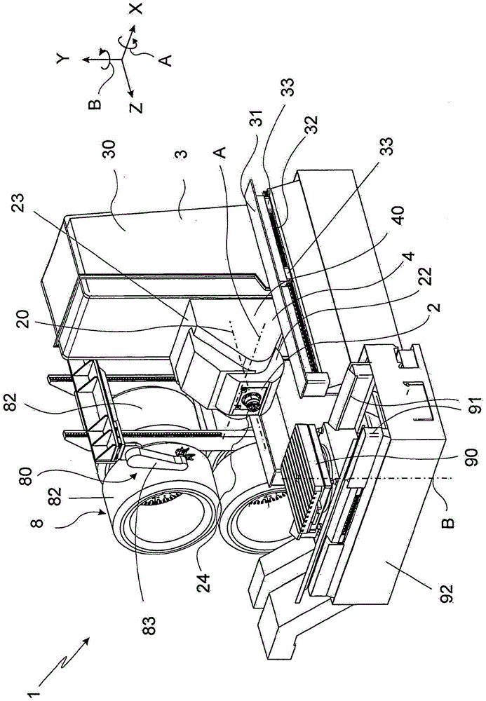
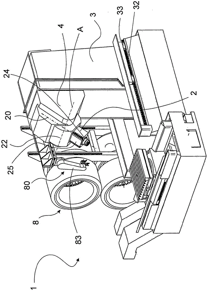
[0053] In the figures, elements that are identical or correspond to one another are marked with the same reference numerals and are therefore not described again as long as this does not serve the purpose. The disclosure content contained in the entire description can be transferred without meaning to the same parts with the same reference signs or the same component designations. Positional indications selected in the description, such as top, bottom, sideways, etc., refer to the immediate description and the illustrated figure and can be transferred to the new position in the event of a position change. Furthermore, individual features or combinations of features from the various exemplary embodiments shown and described constitute per se independent, inventive or inventive solutions.

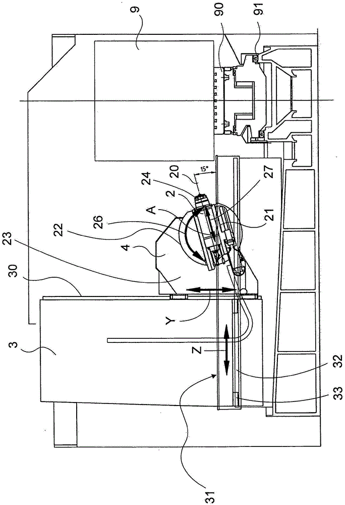
[0054] exist Figure 1a , b shows by way of example that the processing machine tool 1 is in two different processing positions. The processing machine tool 1 is used for machining a workpi...


PUM


Abstract

The invention relates to a machine tool having a motor spindle for machining a workpiece (9). The machine tool is provided with a motor spindle (2) used for rotating around an axis of the spindle (20) and driving a cutter. The motor spindle (2) is supported by a support (3). A rotary bearing (4) is provided on the support (3) and the motor spindle (2) can be swivelled and positioned on the rotary bearing about a first axis (A) of rotation. On the motor spindle (2) is a linear guiding device (21) according to the invention, which allows an advancing movement of the tool parallel to the spindle axis (20). The machine tool has a workpiece bracket (90) which can be moved and positioned along a preferably horizontally oriented workpiece guiding device (30) and can be rotated and positioned about a second axis (Y) of rotation

Description

technical field [0001] The invention relates to a machine tool for machining workpieces, wherein the machine tool has a motor spindle for driving a tool in rotation around the spindle axis, and the motor spindle is carried by a support. Background technique [0002] Processing machines of the same type have been known for a long time. They are used for many, often complex, machining operations on workpieces, such as cylinder heads or transmission housings. The same type of processing machine tool is used here as part of a processing line connected to one another via corresponding coupling or transport means or also individually as a universal machine tool. Here, it is advantageous for efficient machining of workpieces that they can be positioned and machined with high precision relative to the tool along a plurality of axes. It is also known here that a linear axis and a rotational axis are distributed between the workpiece and the motor spindle. Machining takes place, fo...

Claims


Application Information

Patent Timeline
IPC IPC(8): B23Q1/48
CPCB23Q1/4804B23C1/12B23Q1/015B23Q1/017B23Q1/4852B23Q1/4866B23Q3/15713B23Q2220/006Y10T409/307672Y10T409/308232Y10T483/1745Y10T483/175
Inventor B·格鲁博
Owner GROB WERKE & K G
Learn More