
Aortic valve device conveyed by catheter

A technology of aortic valve and catheter, applied in the field of medical devices, to achieve the effect of reducing paravalvular leakage and precise positioning

Inactive Publication Date: 2016-04-20
BEIJING MED ZENITH MEDICAL SCI CORP LTD
View PDF10 Cites 16 Cited by
  • Summary
  • Abstract
  • Description
  • Claims
  • Application Information

AI Technical Summary

Problems solved by technology

[0004] It is an object of the present invention to provide a transcatheter aortic valve device for implantation into an in situ aortic valve diseased due to aortic stenosis or regurgitation or regurgitation , to solve the problem of accurate positioning of the aortic valve device; further, to solve the problem of adapting to various diseases, such as aortic valve stenosis or regurgitation or regurgitation or bivalvation and other diseases

Method used


Image

  • Aortic valve device conveyed by catheter
  • Aortic valve device conveyed by catheter
  • Aortic valve device conveyed by catheter

Examples


Embodiment Construction

[0031] The present invention provides an aortic valve device delivered through a catheter, the aortic valve device is used to be implanted into the in situ aortic valve caused by aortic stenosis or insufficiency or regurgitation, to solve the problem of The problem of accurate positioning of the aortic valve device; further, to solve the problem of adapting to various diseases, such as aortic valve stenosis or insufficiency or regurgitation or bivalve.

[0032] The embodiments of the present invention will be described in further detail below in conjunction with the accompanying drawings.

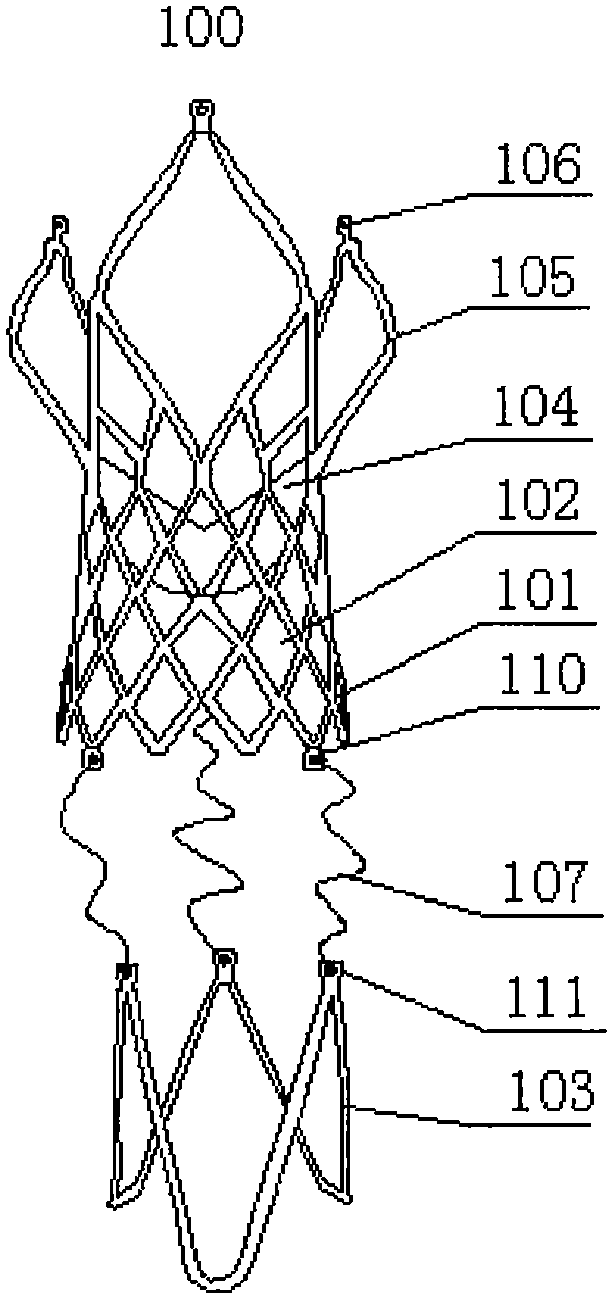
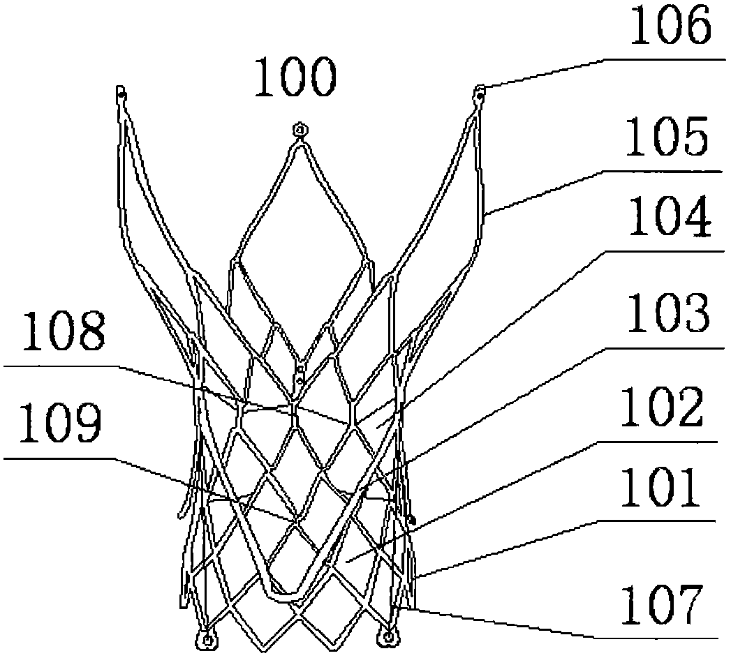
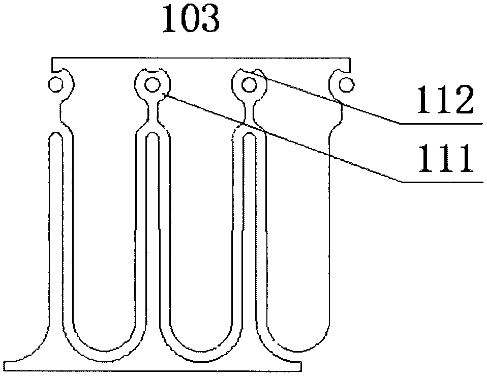
[0033] Such as Figure 1 to Figure 3 A kind of aortic valve device 100 shown is used to be implanted into the in situ aortic valve caused by aortic stenosis or regurgitation. The aortic valve device includes: main stent; The leaflet 104 on the inner side of the middle part of the main support; and the skirt 102 fixed along the inner periphery of the main support and fixed with the leaflet ...


PUM

PropertyMeasurementUnit
Inclinationaaaaaaaaaa

Abstract

The invention provides an aortic valve device conveyed by a catheter. The aortic valve device comprises a main support, wave leaflets and a skirt. The valve leaflets are fixed to the inner side of the middle of the main support. The skirt is fixed along the periphery of the inner side of the main support and fixed to the valve leaflets. An upper horn mouth structure in a three-valve form is formed by the upper end of the main support. Three circular connection jaws used for loads of the main support are arranged at the tail end of the horn mouth structure. A lower horn mouth structure used for reducing outward expanding of perivalvular leakage is arranged at the bottom end of the main support. Three lower end circular connection jaws are arranged at the lower end of the lower horn mouth structure. The aortic valve device further comprises a positioning ring located on the lower side of the main support and used for conducting positioning. The positioning ring comprises three V-shaped or U-shaped arc sections. The ends of the V-shaped or U-shaped arc sections are connected to form an annular shape. Three positioning circular connection jaws are formed at the ends. The lower end circular connection jaws are connected with the corresponding positioning circular connection jaws through flexible positioning lines respectively.

Description

technical field [0001] The invention relates to the field of medical devices, in particular to an aortic valve device delivered through a catheter. Background technique [0002] With the aggravation of population aging, senile valvular disease and valvular disease caused by coronary heart disease and myocardial infarction are becoming more and more common. Surgery, that is, artificial heart valve replacement or valvuloplasty, is the radical cure for valvular heart disease. However, for some patients who are elderly, have multiple comorbidities, or have a history of surgical thoracotomy, the mortality rate of surgical thoracotomy is very high. high. In recent years, with the progress of interventional therapy technology, the epoch-making technology of transcatheter artificial valve has pushed interventional surgery to the technical peak, and tried to solve all the shortcomings of surgical valve replacement. In 2002, the success of the first transcatheter artificial valve re...

Claims


Application Information

Patent Timeline
IPC IPC(8): A61F2/24
CPCA61F2/2418A61F2/2466A61F2210/0014A61F2220/0008
Inventor 代高旭周庆亮孟坚可大年史欢欢李阳黄韬杨宇霆
Owner BEIJING MED ZENITH MEDICAL SCI CORP LTD
Learn More