General assembly line body for vacuum pump assembly line

An assembly line and vacuum pump technology, applied in assembly machines, metal processing equipment, manufacturing tools, etc., can solve the problems of long time consumption, large space occupation, low production efficiency, etc., and achieve the effect of reducing labor consumption and improving production efficiency.

Inactive Publication Date: 2016-04-20
CHONGQING YUNHAI MACHINERY MFG
View PDF0 Cites 4 Cited by
  • Summary
  • Abstract
  • Description
  • Claims
  • Application Information

AI Technical Summary

Problems solved by technology

[0005] In the prior art, the above steps are not streamlined, but each step has its own position, and the workpiece needs to be manually transported to the position of each step, so this device has the following disadvantages: 1) It requires a lot of manpower, and It takes a long time and the production efficiency is low; 2) The devices for each step are messy and take up a lot of space

Method used


Image

  • General assembly line body for vacuum pump assembly line
  • General assembly line body for vacuum pump assembly line
  • General assembly line body for vacuum pump assembly line

Examples


Embodiment Construction

[0020] In order to make the technical means, creative features, goals and functions achieved by the present invention clearer and easier to understand, the present invention will be further elaborated below in conjunction with the accompanying drawings and specific embodiments:

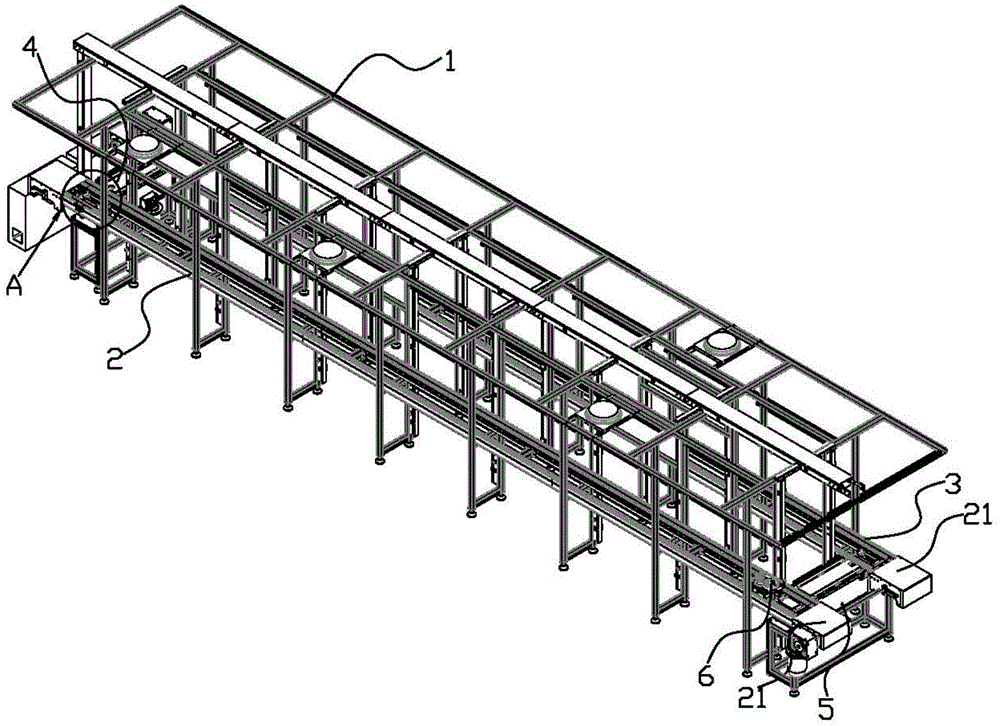
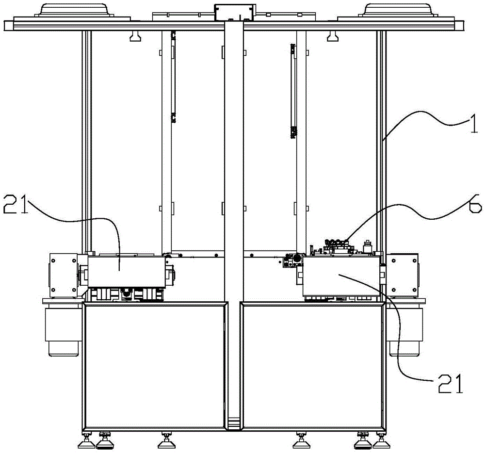
[0021] Such as Figure 1 to Figure 5 As shown, this embodiment provides a general assembly line body for a vacuum pump assembly line, including a load-bearing stand 1 .

[0022] A first slide rail 2 and a second slide rail 3 are horizontally installed on the load-bearing stand 1, and the first slide rail 2 and the second slide rail 3 are parallel to each other. The driving direction of the first slide rail 2 is perpendicular to the first conveyor belt 4 , and a second conveyor belt 5 is connected between the discharge end of the first slide rail 2 and the feed end of the second slide rail 3 .

[0023] The first conveyor belt 4, the first slide rail 2, the second slide rail 3 and the second conveyor b...


PUM


Abstract

The invention discloses a general assembly line body for a vacuum pump assembly line. The general assembly line body comprises a vertical bearing frame, wherein the vertical bearing frame is horizontally provided with a first sliding rail and a second sliding rail which are parallel to each other; a first conveying belt vertical to the transmission direction of the first sliding rail is connected beside the feeding end of the first sliding rail, and a second conveying belt is connected between the discharging end of the first sliding rail and the feeding end of the second sliding rail; the first conveying belt, the first sliding rail, the second sliding rail and the second conveying belt are slidably provided with a station plate, and the station plate is used for bearing parts of a vacuum pump and is capable of sliding relative to the vertical bearing frame under the drive of the first sliding rail and the second sliding rail; and the first sliding rail is driven by a first traversing mechanism, and the second sliding rail is driven by a second traversing mechanism. The general assembly line body has the beneficial effects that the parts of the vacuum pump are sequentially conveyed in all steps for preparing the vacuum pump, and meanwhile the general assembly line body is mounted in a relatively narrow production workshop.

Description

technical field [0001] The invention relates to vacuum pump manufacturing equipment, in particular to a general assembly line body used in a vacuum pump assembly line. Background technique [0002] The steps of preparing the vacuum pump include: the first half step and the second half step. [0003] The first half steps include: 1) Detect the gap between the rotor, valve plate, and scraper on the mounting surface of the pump cover; 2) Manually install the pump cover, install O-rings, and tighten the screws; 3) Automatically tighten the screws; 4 ) initial inspection of aerodynamic torque and performance; 5) performance test; 6) assembly cleaning; and, 7) laser marking. [0004] The second half of the steps include: 8) Manually remove the upper pump body, rotor, pump cover, valve plate and scraper assembly of the vacuum pump that has been inspected; 9) Automatic feeding, press-fitting positioning pins; 10) Manual installation by tightening screws 11) automatic screw tighten...

Claims


Application Information

Patent Timeline
Patent Type & Authority Applications(China)
IPC IPC(8): B23P21/00
CPCB23P21/00
Inventor 王帆王邦奎何万飞金润罗保田
Owner CHONGQING YUNHAI MACHINERY MFG
Why Eureka
Try Eureka