
A piston sheath device for pneumatic conveying of materials

A pneumatic conveying and pneumatic conveying technology, applied in the direction of conveyor, transportation and packaging, etc., can solve the problems of high cost of use, sample bottle damage, high maintenance cost, etc., and achieve low cost, simple production process, and guaranteed physical characteristics and precision Effect

Active Publication Date: 2018-07-03
HUNAN SUNDY SCI & TECH DEV
View PDF7 Cites 0 Cited by
  • Summary
  • Abstract
  • Description
  • Claims
  • Application Information

AI Technical Summary

Problems solved by technology

The staff needs to design the sample bottle according to the size of the pipe, or design the pipe according to the size of the sample bottle. There are problems such as difficult processing of the pipe and sample bottle, high cost of use, and very inconvenient operation.
The second is that this method does not protect the sample bottle, and the air pressure directly acts on the sample bottle, which may easily cause serious consequences such as sample bottle rupture or even sample bottle explosion.
However, due to the high-speed transmission, the sample bottle is easy to fall off from the push piece during the transmission process. For example, in the stage of a straight-line drop transmission pipeline, the sample bottle drops faster than the push piece due to gravity and acceleration, resulting in a drop with the push piece. Push pieces fall off
The detached sample bottle can no longer be fixedly connected with the push piece, causing the sample bottle to lose protection and directly rub against the pipeline. During high-speed transmission (10 meters per second), the friction heat will cause the sample water in the sample bottle to be analyzed or oxidized, affecting Sample physical properties and precision
At the same time, the sample bottle is easy to collide with the pipeline during the high-speed transmission process, resulting in damage to the sample bottle and sample leakage
[0007] (3) In some existing pipeline transportation methods, when there are foreign objects in the transmission pipeline (the foreign objects may be sample residues, sample leaks, or ice cubes, because when the temperature is very low, the inner wall of the pneumatic transmission pipeline is prone to appear If the foreign matter is not cleaned in time, it will affect the normal operation of the sample bottle and seriously affect the delivery efficiency of the sample
And because the pneumatic transmission pipeline is very long and very small (people cannot enter), it is very difficult to clean once foreign objects appear in the transmission pipeline
However, if it is not cleaned in time, the sample bottle may be stuck in the transmission pipeline. Once it is blocked, it will be more difficult to clean the pipeline and the maintenance cost will be extremely high.

Method used


Image

  • A piston sheath device for pneumatic conveying of materials
  • A piston sheath device for pneumatic conveying of materials
  • A piston sheath device for pneumatic conveying of materials

Examples


specific Embodiment 1

[0039] Specific embodiment 1: as Figure 4 and Figure 5 As shown, in this embodiment, the other end of the piston sheath body 2 is provided with a foreign matter removal part 24. The foreign matter 5 in the transmission pipe 1 is pushed and removed out of the pipe under the action of thrust. In this embodiment, the foreign matter removal part 24 includes a shovel-shaped edge provided on one end of the piston sheath body 2 , and the shovel-shaped edge is arranged along the circumference of the piston sheath body 2 .

[0040] When there is a foreign object 5 in the pipeline (the foreign object 5 may be sample residue, sample leakage, or ice cubes, because when the temperature is very low, the inner wall of the pneumatic transmission pipeline 1 is prone to condensation of gas into ice), the high-speed The foreign matter removal part 24 of the conveying piston sheath body 2 can scoop up the foreign matter 5 in the pipeline and push it forward until it is cleared out of the pipe...

specific Embodiment 2

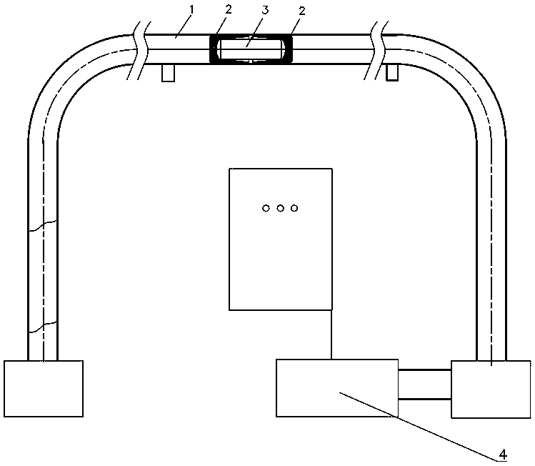
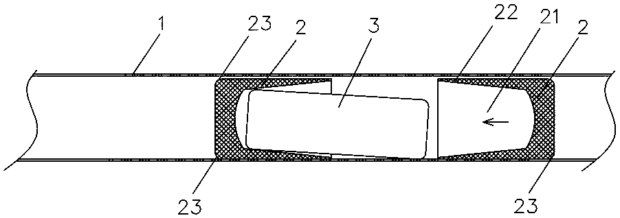
[0041] Specific embodiment 2: as Image 6 As shown, in this embodiment, the piston sheath body 2 is a two-way driving piston sheath, and both ends of the piston sheath body 2 are provided with matching protective chambers 21 and guide parts 22, that is, the piston sheath body 2 Both ends can carry and protect an object 3 to be conveyed. The operator can set a piston sheath body 2 in the pneumatic transmission pipeline 1 to push or pull the object 3 to be conveyed to complete the pneumatic transmission; it is also possible to set more than two piston sheath bodies 2 in the pneumatic transmission pipeline 1 to sandwich the material to be transported. Conveyor 3 is conveyed pneumatically. At the same time, it is also possible to realize synchronous transmission of multiple objects to be conveyed 3 at the same time. It is only necessary to connect multiple piston sheath bodies 2 and multiple objects to be conveyed 3 in series, that is, to set each object to be conveyed 3 in two a...


PUM


Abstract

The invention discloses a piston jacket device for pneumatic conveying of materials. The piston jacket device comprises a piston jacket body arranged in a pneumatic conveying pipeline and used for driving to-be-conveyed materials to complete pneumatic conveying, a concave protecting cavity is arranged at on end, for driving the to-be-conveyed materials, of the piston jacket body and used for carrying the to-be-conveyed materials to enable the same not to contact with the pneumatic conveying pipeline, a guide portion is arranged at an opening end of the protecting cavity, and when the piston jacket body pushes the to-be-conveyed materials, the guide portion contacts with the to-be-conveyed materials and guides the same into the protecting cavity under thrust action. The piston jacket device has the advantages of being capable of protecting the to-be-conveyed materials, capable of realizing automatic protection continuation with the to-be-conveyed materials which break away, convenient and quick to convey, high in safety and capable of guaranteeing physical characteristics and accuracy of samples.

Description

technical field [0001] The invention mainly relates to the field of equipment for collecting and processing material samples, and in particular to a piston sheath device for pneumatically conveying materials. Background technique [0002] For the sampling, sample preparation, and testing of material (such as ore, coal) samples, each country has mandatory standards, and the sampling and processing of samples must be carried out in accordance with the standards. The principle of sample sampling, sample preparation, and testing work process is to gradually reduce the particle size and quality of the collected samples without destroying the representativeness of the sample, until it meets the particle size and quality of the sample in the laboratory test ( Weight) accuracy requirements, and then carry out relevant laboratory analysis on the samples that meet the requirements. [0003] For example, taking coal sampling as an example, it is actually a sampling and analysis proces...

Claims


Application Information

Patent Timeline
Patent Type & Authority Patents(China)
IPC IPC(8): B65G51/06
CPCB65G51/06
Inventor 朱先德朱青任率刘清海王芹
Owner HUNAN SUNDY SCI & TECH DEV
Learn More