A hydraulically driven high-pressure rotary grinding head for radial drilling in casing

A radial drilling and hydraulic drive technology, applied in drill bits, drilling tools, drilling equipment, etc., can solve problems such as easy stoppage and fracture, low milling efficiency, and difficulty in intuitively judging whether the casing window is successful or not. , to eliminate the reduction of cutting efficiency, not easy to wear, and to achieve good reliability.

Active Publication Date: 2017-12-22
CHINA PETROCHEMICAL CORP +1
View PDF7 Cites 0 Cited by
  • Summary
  • Abstract
  • Description
  • Claims
  • Application Information

AI Technical Summary

Problems solved by technology

[0006] The purpose of the present invention is to provide a hydraulically driven casing inner diameter in order to overcome the problems of low milling efficiency, easy stoppage and breakage of the existing milling bit, and the difficulty of intuitively judging whether the casing window is successfully opened. Drilling high pressure rotary grinding head

Method used


Image

  • A hydraulically driven high-pressure rotary grinding head for radial drilling in casing
  • A hydraulically driven high-pressure rotary grinding head for radial drilling in casing

Examples


Embodiment 1

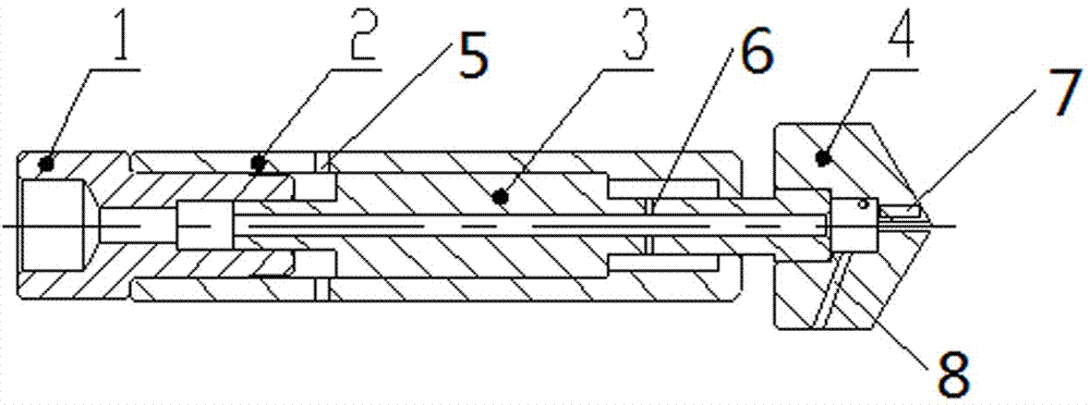
[0018] Such as figure 1 Shown is a hydraulically driven high-pressure rotary grinding head for radial drilling in the casing, which includes four parts: a lower joint 1 , a body 2 , a core 3 and a grinding head 4 . The inner cavity of the main body 2 can accommodate the core part 3, and the surface of the main body 2 has radially distributed straight holes 5 communicating with the inner cavity of the main body 2. The lower joint 1 and the main body 2 are connected together by threads, and there is a cavity inside the lower joint 1, which can Hold the tail of the core 3, the core 3 can move in this cavity, the middle part of the core 3 is cylindrical, the surface is smooth, and matches the inner cavity of the body 2, the core 3 has through holes inside, and the surface has radial distribution The straight hole 6 communicates with the internal through hole, and the front part is connected with the grinding head 4 through threads. The two can move relative to the lower joint 1 th...

Embodiment 2

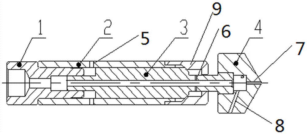
[0020] Such as figure 2 Shown is another hydraulically driven high-pressure rotary grinding head for radial drilling in the casing, including four parts: the lower joint 1 , the body 2 , the core 3 and the grinding head 4 . The body 2 is composed of a cylinder body and a front block 9 of the body. The two parts are connected together by threads, and a groove is formed at the junction of the two parts. The inner cavity of the body 2 can accommodate the core 3. The surface of the body 2 has a vertical straight The hole 5 communicates with the inner cavity of the body 2, and the lower joint 1 and the main body 2 are connected together by threads. There is a cavity inside the lower joint 1, which can accommodate the tail of the core 3, and the core 3 can move in this cavity. The middle part of part 3 is cylindrical, with a smooth surface, matching with the inner cavity of the body 2, with a slope on the front end of the cylinder, matching with the inclined surface of the inner ca...


PUM


Abstract

The invention discloses a hydraulically driven high-pressure rotary grinding head for radial drilling in casing pipes, which includes a lower joint, a body, a core and a grinding head. The tail of the body is connected; the core is provided with an axial through hole, and the core is set in the body, and the expanded diameter section of the core forms a clearance fit with the outer body, and the tail of the core forms an axial cavity with the lower joint or the body. Sealing and sliding fit, the end of the core is connected with the grinding head; the end of the grinding head is conical, and the grinding head is provided with spray holes in the front and rear directions, and the spray holes are connected with the cavity inside the grinding head; the body and the core are both There are radially distributed straight holes, the straight holes of the body communicate with the inner cavity of the body, and the straight holes of the core communicate with the through holes of the core. When the invention performs jet drilling, the pump is turned on, and the grinding head rotates at high speed to generate high-pressure water jets to spray the rock formation. At the same time, the grinding head moves forward under the action of self-traction force. Finish.

Description

technical field [0001] The invention relates to the field of downhole drilling tools, in particular to a hydraulically driven high-pressure rotary grinding head suitable for opening windows in radial drilling casings. Background technique [0002] The hydraulic jet radial drilling technology uses a special milling bit to drill through the casing, and then uses high-pressure water jets to spray in different directions and depths of the oil layer, thereby drilling multiple horizontal small-diameter wells. It can increase the length of the wellbore in the oil reservoir, expand the oil drainage area, and increase the recovery rate; it can reuse the upper well section and reduce the drilling cost; it can reduce the cost of oil well management and environmental protection. The hydrojet radial drilling technology is of great significance to the production increase of oil and gas wells, especially for tapping the potential of old wells. [0003] When using hydraulic jet radial dril...

Claims


Application Information

Patent Timeline
Patent Type & Authority Patents(China)
IPC IPC(8): E21B10/00E21B12/02
Inventor 聂云飞张俊杰韩通吴仲华蔡文军张辉左灵田宗正朱杰然张锐
Owner CHINA PETROCHEMICAL CORP
Why Eureka
Try Eureka