
A shielded motor main pump pump casing guide device

A shielded motor main pump and flow guiding device technology, which is applied to parts, pumps, pump components, etc. of pumping devices for elastic fluids, can solve the problems of complex structure and functional loss of liquid pumps, and achieve simple structure and reduced Flow resistance, reasonable design effect

Active Publication Date: 2018-05-25
CHINA UNITED ENG
View PDF7 Cites 2 Cited by
  • Summary
  • Abstract
  • Description
  • Claims
  • Application Information

AI Technical Summary

Problems solved by technology

[0003] Now there is also a structure that can play a diversion effect on the pump body. For example, in the Chinese patent with the publication date of December 10, 2008 and the publication number CN201162721, a pump casing synchronously rotating diversion liquid pump is disclosed. The pump adopts the synchronous rotation of the rotating pump casing and the impeller to solve the problem of certain functional loss caused by friction between the rotating liquid in the pump and the inner wall of the pump casing due to the static pump casing of the liquid pump, but the structure of the liquid pump is relatively complicated.

Method used


Image

  • A shielded motor main pump pump casing guide device
  • A shielded motor main pump pump casing guide device
  • A shielded motor main pump pump casing guide device

Examples


Embodiment Construction

[0047]The present invention will be further described in detail below in conjunction with the accompanying drawings and examples. The following examples are explanations of the present invention and the present invention is not limited to the following examples.

[0048] Example.

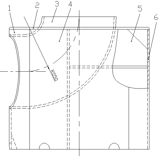
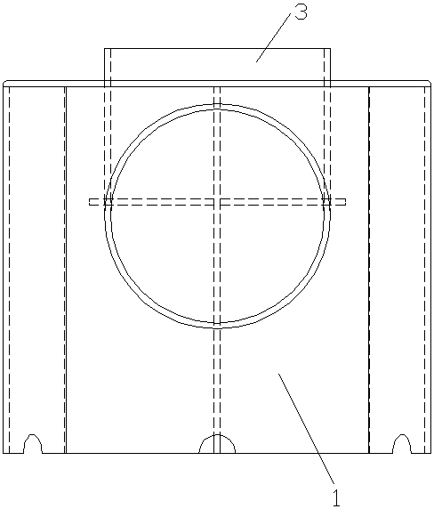
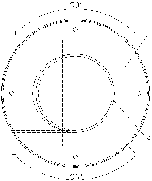
[0049] see Figure 1 to Figure 30 , the shielded motor main pump casing guide device in this embodiment includes a cylinder, an upper cover plate 2, a guide elbow 3, and a main support plate 5 that supports the guide elbow 3 vertically and laterally, Two vertical support plates 7 for vertically supporting the diversion elbow 3 , and two horizontal support plates 8 for laterally supporting the diversion elbow 3 .

[0050] The barrel in this embodiment includes a barrel front piece 1, a barrel back piece 6 and two barrel side pieces 4, and the barrel front piece 1, the barrel back piece 6 and the two barrel side pieces 4 are radius Equal arc-shaped structure, the degrees of arcs of the cylinder fron...


PUM


Abstract

The invention relates to a pump shell flow guiding device of a canned motor main pump. At present, a pump shell flow guiding device, capable of forming a stable flow field and reducing flow resistance of fluid when the fluid passes a pump shell, of a canned motor main pump does not exist. The flow guiding device is characterized in that the device comprises a cylinder, an upper cover plate, a flow guiding bend, a main supporting plate, two vertical supporting plates and two horizontal supporting plates; the cylinder comprises a cylinder front element, a cylinder rear element and two cylinder side elements; the cylinder front element, one cylinder side element, the cylinder rear element and the other cylinder side element are sequentially fixed end to end to form a cylindrical cylinder; the upper cover plate is fixed to the top of the cylinder; the main supporting plate, the two vertical supporting plates and the two horizontal supporting plates are fixed into the cylinder, the flow guiding bend is in an arc-shaped structure and is located in the cylinder, an outlet of the flow guiding bend and a transverse opening of the cylinder front element are fixed, and an inlet of the flow guiding bend is connected into a longitudinal opening of the upper cover plate in a penetrating mode. By means of the pump shell flow guiding device, a stable flow field can be formed, and flow resistance of fluid can be reduced when the fluid passes the pump shell.

Description

technical field [0001] The present invention relates to a flow guide device, in particular to a shielded motor main pump casing flow guide device, which is mainly used in places with large spaces where the front and rear pipelines are irregularly connected, and is used to form a stable flow field to reduce flow resistance . Background technique [0002] The large-scale advanced pressurized water reactor nuclear power plant is a sub-item of one of the 16 national major scientific and technological projects determined in the "National Medium and Long-Term Science and Technology Development Program (2006-2020)". Reactor coolant pump, as one of the key equipment in the primary circuit system of the pressurized water reactor nuclear power plant, plays an important role in the energy conversion of the nuclear power plant, and is known as the heart of the reactor cooling system. At present, the main pumps used in domestic one-million-kilowatt nuclear power plants are all foreign d...

Claims


Application Information

Patent Timeline
Patent Type & Authority Patents(China)
IPC IPC(8): F04D29/40
CPCF04D29/406F05D2240/12
Inventor 章煜君曾鹏邓凯
Owner CHINA UNITED ENG
Learn More