Infrared humidifier

A humidifier and infrared technology, used in air humidification systems, heating methods, lighting and heating equipment, etc., can solve the problems of large starting current, rapid heating, and shortened life of infrared lamps, and achieve the effect of prolonging life.

Active Publication Date: 2016-04-20
GREE ELECTRIC APPLIANCES INC
View PDF8 Cites 28 Cited by
  • Summary
  • Abstract
  • Description
  • Claims
  • Application Information

AI Technical Summary

Problems solved by technology

[0004] However, the start-up current at the moment when the infrared lamp is turned on is relatively large, and frequently starting the infrared lamp will shorten the service life of the infrared lamp
Since the infrared lamp is a pure resistive load, its cold-state resistance is low, and the starting current of the infrared lamp is relatively large when it is powered on (for example, the starting current of a 1.5KW infrared lamp is as high as 40A-50A, and the normal operating c

Method used


Image

  • Infrared humidifier
  • Infrared humidifier
  • Infrared humidifier

Examples


Embodiment 1

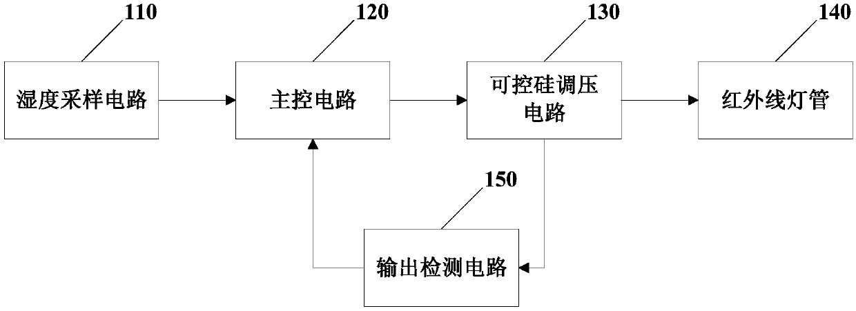
[0039] figure 1 The functional block diagram of an infrared humidifier provided in Embodiment 1 of the present invention specifically includes:

[0040] Infrared lamp tube 140, humidity sampling circuit 110, main control circuit 120, output detection circuit 150 and thyristor voltage regulating circuit 130;

[0041] The humidity sampling circuit 110 is electrically connected to the main control circuit 120 for collecting environmental humidity data, and inputting the environmental humidity data to the main control circuit 120;

[0042] The main control circuit 120 is electrically connected to the thyristor voltage regulating circuit 130 and the output detection circuit 150 respectively, and is used to determine the control signal of the thyristor voltage regulating circuit 130 according to the ambient humidity data and output parameters, Outputting the control signal to the thyristor voltage regulating circuit 130;

[0043] The output detection circuit 150 is electrically co...

Embodiment 2

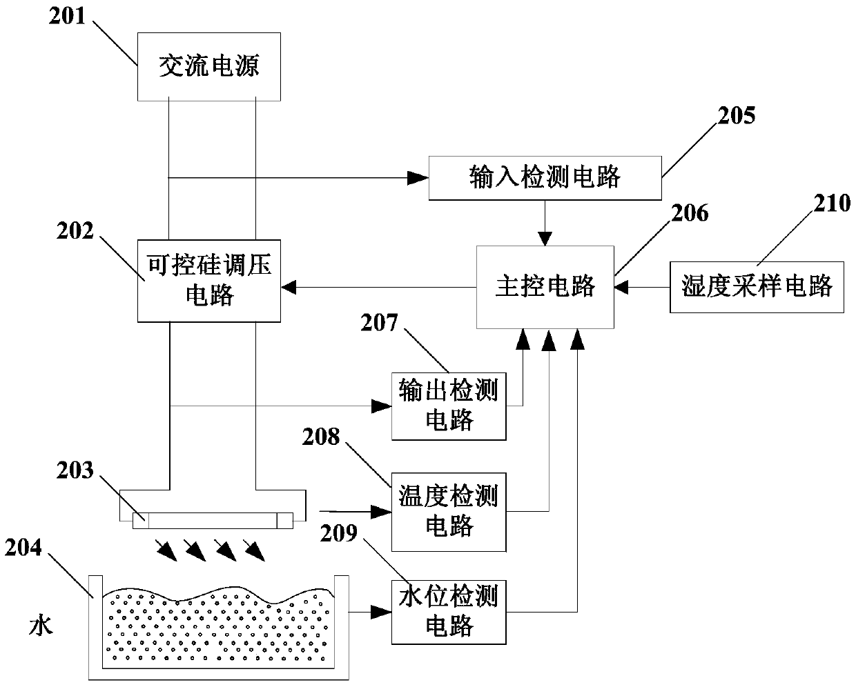
[0052] Figure 2a It is a structural schematic diagram of an infrared humidifier in Embodiment 2 of the present invention. The technical solution of this embodiment further adds technical features such as input detection circuit 205, temperature detection circuit 208 and water level detection circuit 209 on the basis of the above embodiments, specifically including:

[0053] An input detection circuit 205 is also provided between the thyristor voltage regulating circuit 202 and the AC power supply 201, for detecting input voltage and input current, and outputting the input voltage and input current to the main control circuit 206 to pass The main control circuit 206 performs overvoltage protection operations, undervoltage protection operations, overcurrent protection operations, phase loss protection operations and interphase unbalance protection operations. The AC power output by the AC power supply 201 is output to the series circuit of the infrared lamp 203 and the thyrist...

Embodiment 3

[0059] image 3 It is a schematic diagram of an output detection circuit of an infrared humidifier in Embodiment 3 of the present invention. The difference between the technical solution of this embodiment and the above embodiments lies in the further limitation of the specific circuit of the output detection circuit. The output detection circuit includes a sampling resistor and an operational amplifier, and the sampling resistor is connected in series in the loop between the infrared lamp and the thyristor voltage regulating circuit. The sampling resistor is also connected in series with the non-inverting input terminal and the inverting input terminal of the operational amplifier, and the output terminal of the operational amplifier is electrically connected with the main control circuit. The output current of the thyristor voltage regulating circuit is input to the main control circuit through the sampling resistor and the operational amplifier. Since the thyristor voltage...


PUM


Abstract

The invention discloses an infrared humidifier which comprises an infrared lamp tube, a humidity sampling circuit, a main control circuit, an output detection circuit and a silicon-controlled voltage regulation circuit. The humidify sampling circuit is electrically connected with the main control circuit and used for collecting environmental humidity data and inputting the same into the main control circuit, the main control circuit is electrically connected with the silicon-controlled voltage regulation circuit and the output detection circuit respectively and used for determining control signals of the silicon-controlled voltage regulation circuit according to the environmental humidity data and output parameters and outputting the control signals to the silicon-controlled voltage regulation circuit, the output detection circuit is electrically connected with the silicon-controlled voltage regulation circuit and used for detecting output parameters of the same and inputting the same into the main control circuit, and the silicon-controlled voltage regulation circuit is electrically connected with the infrared lamp tube and used for regulating the output parameters of the silicon-controlled voltage regulation circuit according to the control circuits to determine heat productivity of the infrared lamp tube. The lamp tube is avoided being frequently switched on and off, so that effects of prolonging service life of the humidifier and saving energy are realized.

Description

technical field [0001] Embodiments of the present invention relate to air-conditioning appliances, in particular to an infrared humidifier. Background technique [0002] The infrared humidifier can quickly evaporate the water in the water tank without boiling, and produce clean steam for air humidification. [0003] Existing infrared humidifiers all have high-power infrared lamps inside, and the infrared lamps will emit high heat after being energized, and use these heat to evaporate the water in the water tank into water vapor, thereby achieving the purpose of humidification. The control method is as follows: when the humidity sensor detects that the indoor humidity is low, the infrared lamp is turned on at full load; when the humidity reaches the set value, the infrared lamp is turned off; Turn on the infrared lamp at full load, and turn off the infrared lamp after the humidity reaches the set value, so as to achieve indoor humidity control. [0004] However, the start-u...

Claims


Application Information

Patent Timeline
IPC IPC(8): F24F6/10F24F11/00
CPCF24F6/105F24F11/0008
Inventor 魏学军薄传海肖凯黄天琦
Owner GREE ELECTRIC APPLIANCES INC
Why Eureka
Try Eureka