An infrared humidifier
A humidifier and infrared technology, used in air humidification systems, heating methods, lighting and heating equipment, etc., can solve the problems of large starting current, infrared lamp impact, no energy saving effect, etc., and achieve the effect of prolonging life.
- Summary
- Abstract
- Description
- Claims
- Application Information
AI Technical Summary
Problems solved by technology
Method used
Image
Examples
Embodiment 1
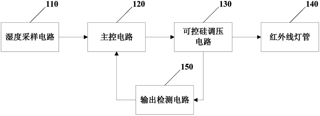
[0039] figure 1 The functional block diagram of an infrared humidifier provided in Embodiment 1 of the present invention specifically includes:
[0040] Infrared lamp tube 140, humidity sampling circuit 110, main control circuit 120, output detection circuit 150 and thyristor voltage regulating circuit 130;
[0041] The humidity sampling circuit 110 is electrically connected to the main control circuit 120 for collecting environmental humidity data, and inputting the environmental humidity data to the main control circuit 120;
[0042] The main control circuit 120 is electrically connected to the thyristor voltage regulating circuit 130 and the output detection circuit 150 respectively, and is used to determine the control signal of the thyristor voltage regulating circuit 130 according to the ambient humidity data and output parameters, Outputting the control signal to the thyristor voltage regulating circuit 130;
[0043] The output detection circuit 150 is electrically co...
Embodiment 2
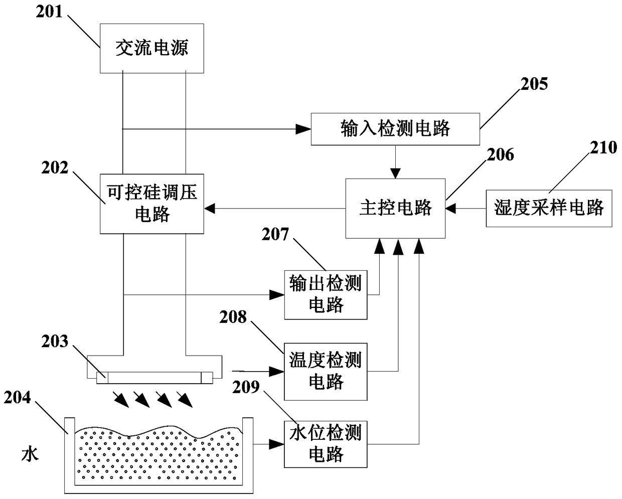
[0052] Figure 2a It is a structural schematic diagram of an infrared humidifier in Embodiment 2 of the present invention. The technical solution of this embodiment further adds technical features such as input detection circuit 205, temperature detection circuit 208 and water level detection circuit 209 on the basis of the above embodiments, specifically including:
[0053] An input detection circuit 205 is also provided between the thyristor voltage regulating circuit 202 and the AC power supply 201, for detecting input voltage and input current, and outputting the input voltage and input current to the main control circuit 206 to pass The main control circuit 206 performs overvoltage protection operations, undervoltage protection operations, overcurrent protection operations, phase loss protection operations and interphase unbalance protection operations. The AC power output by the AC power supply 201 is output to the series circuit of the infrared lamp 203 and the thyrist...
Embodiment 3
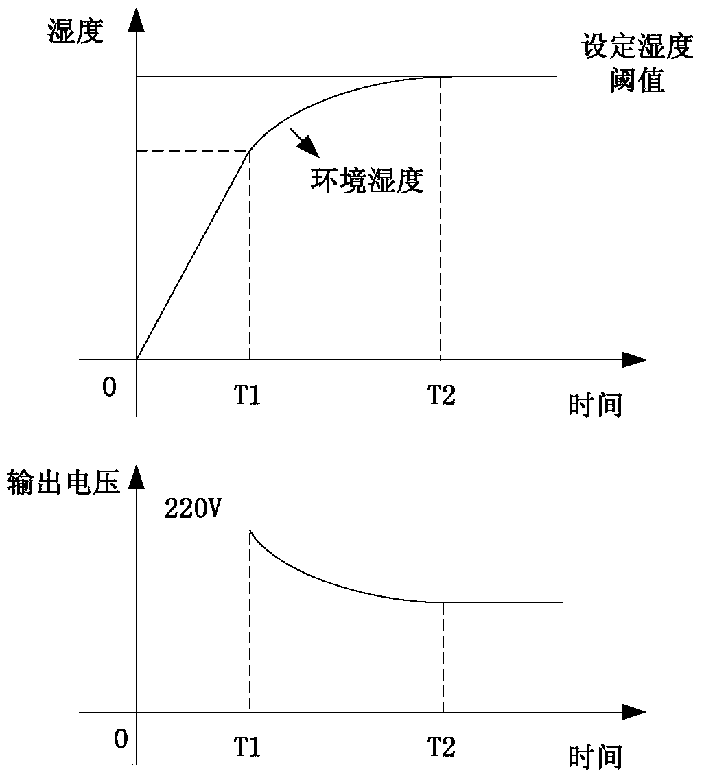
[0059] image 3 It is a schematic diagram of an output detection circuit of an infrared humidifier in Embodiment 3 of the present invention. The difference between the technical solution of this embodiment and the above embodiments lies in the further limitation of the specific circuit of the output detection circuit. The output detection circuit includes a sampling resistor and an operational amplifier, and the sampling resistor is connected in series in the loop between the infrared lamp and the thyristor voltage regulating circuit. The sampling resistor is also connected in series with the non-inverting input terminal and the inverting input terminal of the operational amplifier, and the output terminal of the operational amplifier is electrically connected with the main control circuit. The output current of the thyristor voltage regulating circuit is input to the main control circuit through the sampling resistor and the operational amplifier. Since the thyristor voltage...
PUM
 Abstract
Description
Claims
Application Information
 - R&D
- Intellectual Property
- Life Sciences
- Materials
- Tech Scout
- Unparalleled Data Quality
- Higher Quality Content
- 60% Fewer Hallucinations
Browse by: Latest US Patents, China's latest patents, Technical Efficacy Thesaurus, Application Domain, Technology Topic, Popular Technical Reports.
© 2025 PatSnap. All rights reserved.Legal|Privacy policy|Modern Slavery Act Transparency Statement|Sitemap|About US| Contact US: help@patsnap.com


