
Power transmission line one-terminal fault location method based on faulty traveling wave distribution characters along the line within two successive time windows

A transmission line, fault location technology, applied in the fault location, detection of faults by conductor type, etc., can solve the problem of high requirements for accurate clock synchronization

Inactive Publication Date: 2016-04-20
KUNMING UNIV OF SCI & TECH
View PDF9 Cites 12 Cited by
  • Summary
  • Abstract
  • Description
  • Claims
  • Application Information

AI Technical Summary

Problems solved by technology

Among them, time-domain single-ended traveling wave ranging requires further research on the reliability of traveling wave head calibration and wave head identification, and the automation of ranging analysis; time-domain double-ended traveling wave Wave arrival time difference, the reliability and accuracy of the initial traveling wave calibration can be easily guaranteed, and there is no need to identify the reflected wave at the fault point, but the double-ended traveling wave ranging requires high precision synchronization of clocks at both ends of the line

Method used


Image

  • Power transmission line one-terminal fault location method based on faulty traveling wave distribution characters along the line within two successive time windows
  • Power transmission line one-terminal fault location method based on faulty traveling wave distribution characters along the line within two successive time windows
  • Power transmission line one-terminal fault location method based on faulty traveling wave distribution characters along the line within two successive time windows

Examples


Embodiment 1

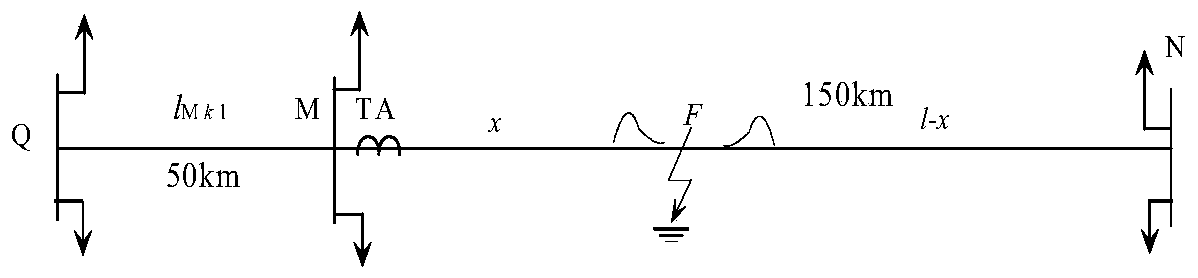
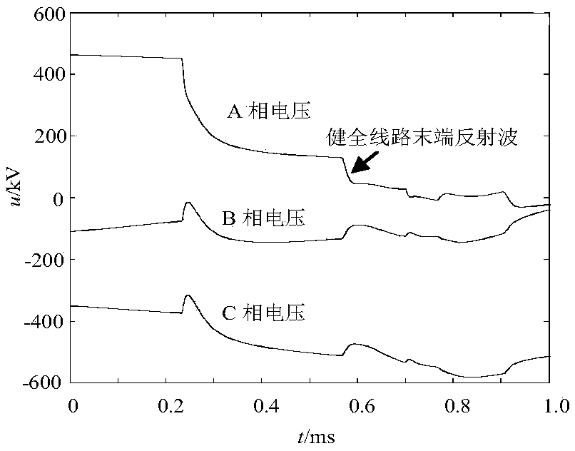
[0085] use as figure 1 In the transmission line shown, the M terminal is in the form of "two-in-one-out" busbar connection, and the sound line l Mk1 = 50km, the end of the sound line is a type III busbar connection, and the length of the faulty line MN is l = 150km. Assuming that a phase A ground fault occurs at a distance of 70km from terminal M within the half-line length of line MN, the traveling voltage and current traveling waves obtained at the measuring terminal are as follows: figure 2 and image 3 shown. The calculation step along the line is 0.1km, respectively in two consecutive time windows [k 0 ,k 0 +l / (2v)] and [k 0 +l / (2v),k 0 +l / v] Calculate the ranging function f of the measuring terminal M uI (x) and f uII (x) The distribution results along the length of the whole line are as follows: Figure 4 and Figure 5 shown. Depend on Figure 4 It can be seen that [k 0 ,k 0 +l / (2v)] time window, f uI (x) mutation point A (x) = 69.8km, and the polarity i...

Embodiment 2

[0087] use as figure 1 In the transmission line shown, the M terminal is in the form of "two-in-one-out" busbar connection, and the sound line l Mk1 = 50km, the end of the sound line is a type III busbar connection, and the length of the faulty line MN is l = 150km. Assuming that a phase A ground fault occurs at a distance of 80km from terminal M beyond the half-line length of line MN, the traveling voltage and current traveling waves obtained at the measuring terminal are as follows: Figure 6 and Figure 7 shown. The calculation step along the line is 0.1km, respectively in two consecutive time windows [k 0 ,k 0 +l / (2v)] and [k 0 +l / (2v),k 0 +l / v] Calculate the ranging function f of the measuring terminal M uI (x) and f uII (x) The distribution results along the length of the whole line are as follows: Figure 8 and Figure 9 shown. Depend on Figure 8 It can be seen that [k 0 ,k 0 +l / (2v)] time window, f uI (x) mutation point B (x) = 69.7km, and the polarity ...


PUM


Abstract

The invention relates to a power transmission line one-terminal fault location method based on faulty traveling wave distribution characters along the line within two successive time windows and belongs to the technical field of the relay protection for an electrical power system. During the fault of a power transmission line, the fault traveling wave data is obtained at the measurement end of the faulted power transmission line, and then the line-mode traveling wave is obtained. The line-mode traveling wave is applied to calculate the distribution of the voltage traveling wave and the distribution of the current traveling wave along the line based on a Bergeron line transfer equation. The voltage traveling wave and the current traveling wave along the line are decomposed along the line direction, so that the directional traveling wave distributed along the line can be obtained. After that, the forward traveling wave is multiplied by the backward traveling wave and then a fault location function is constructed through the integral method within an observation time window. Therefore, the fault location function is realized. According to the technical scheme of the invention, the method realizes the fault location function for the power transmission line, and is simple in principle, wherein the wave head of the fault traveling wave is free from being calibrated. Meanwhile, the influence of the fault instantaneity, the fault transition resistance variation and other factors is avoided. The fault location result of the method is accurate and reliable.

Description

technical field [0001] The invention relates to a single-end fault distance measurement method of a transmission line based on the distribution characteristics of fault traveling waves along the line in two consecutive time windows, and belongs to the technical field of electric power system relay protection. Background technique [0002] Fault location methods are divided into impedance method, fault analysis method and traveling wave method according to the principle. Traveling wave ranging uses the propagation time of the fault traveling wave between the busbar and the fault point to measure the fault distance. Its ranging accuracy is high and its application range is wide. Most of the current traveling wave ranging methods are based on the time-domain characteristics of the fault traveling wave and observe, describe and calibrate the wave head on the time axis, as well as calculate the fault distance. Among them, time-domain single-ended traveling wave ranging requires ...

Claims


Application Information

Patent Timeline
Patent Type & Authority Applications(China)
IPC IPC(8): G01R31/08
CPCG01R31/081
Inventor 束洪春余多田鑫萃
Owner KUNMING UNIV OF SCI & TECH
Learn More