
Device for calibrating space charge density measurement equipment

A space charge and density measurement technology, applied in the direction of measuring devices, measuring electrical variables, instruments, etc., can solve problems such as easy to generate ozone, damage the environment, and poor safety, and achieve the effect of safe and convenient use, clear principle, and simple structure

Active Publication Date: 2016-04-20
CHINA ELECTRIC POWER RES INST +2
View PDF6 Cites 4 Cited by
  • Summary
  • Abstract
  • Description
  • Claims
  • Application Information

AI Technical Summary

Problems solved by technology

However, my country has not established corresponding measurement standards, and it is very necessary to test the correctness and reliability of its measurement data
[0003] The existing technology mainly uses the corona method to generate charges to calibrate the space charge density measurement equipment, but this method needs to use a high voltage source and is very easy to generate ozone, which has poor safety and damages the environment

Method used


Image

  • Device for calibrating space charge density measurement equipment
  • Device for calibrating space charge density measurement equipment
  • Device for calibrating space charge density measurement equipment

Examples


Embodiment 1

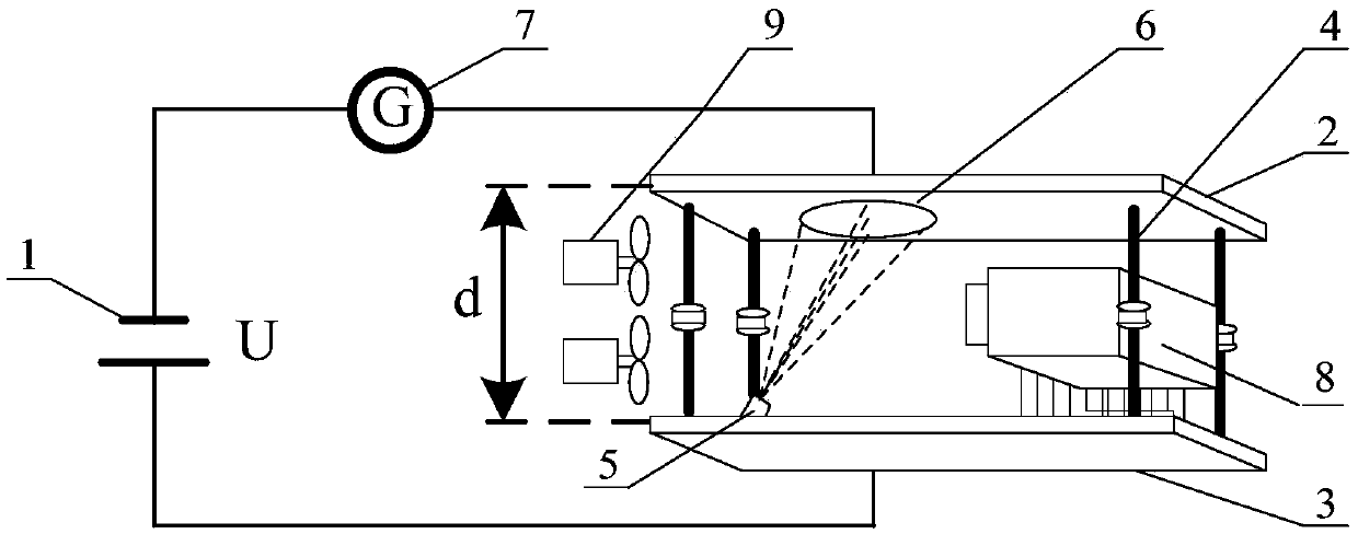
[0039] The space charge measurement equipment of ion counter method or charge screening method is calibrated by using the calibration device of the present invention.

[0040] The power supply adopts a controllable DC power supply, and the positive and negative electrodes of the voltage are respectively connected to the lower plate and the upper plate through wires to form a standard electric field; the upper plate is irradiated with an arc lamp, and electrons are generated in the irradiated area, and the electrons are under the action of the electric field force Moving down the plate, electrons and molecules combine to form negative ions during the movement; observe the deflection of the galvanometer, and when the deflection of the galvanometer is stable, turn on the ion counter method or the space charge measurement device of the charge screening method on the right platform to measure The charge density (negative ion density) between the upper plate and the lower plate is th...

Embodiment 2

[0042] The space charge measuring equipment based on the Faraday cage method is calibrated by using the calibration device of the present invention.

[0043] The difference from Example 1 is that the space charge density measuring instrument based on the Faraday cage method of this embodiment cannot draw charges into the space charge measurement device, and needs to blow ions to the space charge measurement device with the help of an external blower fan, thereby performing calibration .


PUM


Abstract

The invention provides a device for calibrating space charge density measurement equipment, and the device comprises a power supply, an upper electrode plate, a lower electrode plate, insulating supporting columns, an arc light lamp, a galvanometer, a platform, and a fan. The positive and negative electrodes of the power supply are respectively connected with the lower and upper electrode plates through wires, and the lower and upper electrode plates are supported by the insulating supporting columns. The galvanometer is disposed on a wire between the negative electrode of the power supply and the upper electrode plate. The arc light lamp is disposed at the edge of the lower electrode plate, and the fan is located above the arc light lamp. The platform of the space charge density measurement equipment is placed between the upper electrode plate and the lower electrode plate. The device is clear in principle, is simple in structure, is low in manufacture cost, is safe and convenient for use, is large in calibration range, and is suitable for the calibration of different types of space charge density measurement equipment. The device is mainly used for the calibration of the space charge density measurement equipment based on an ion counting method, a Faraday cage method, a charge screening method and a probe array method.

Description

technical field [0001] The invention relates to a calibration device, in particular to a calibration device for space charge density measuring equipment. Background technique [0002] The synthetic electric field under the DC transmission line is an important parameter of the electromagnetic environment of the DC transmission line. The electric field formed by the ions generated by the corona of the DC transmission line is a part of the synthetic field strength and has a great influence on the synthetic field strength value. In order to study the relationship between the space charge density in my country's special environment and the ground synthetic electric field, it is necessary to measure the space charge density. However, my country has not established corresponding measurement standards, and it is very necessary to test the correctness and reliability of its measurement data. [0003] The existing technology mainly uses the corona method to generate charges to calibr...

Claims


Application Information

Patent Timeline
Patent Type & Authority Applications(China)
IPC IPC(8): G01R35/00
CPCG01R35/005
Inventor 杨晓洪谢莉袁海文张月魁鞠勇陆家榆葛瑞祎罗晓川吕建勋
Owner CHINA ELECTRIC POWER RES INST
Learn More