BOG recovering method and device

A recovery method and technology of a recovery device, applied in the field of BOG recovery, can solve the problems of complex process, difficult realization by enterprises, and small scope of application, and achieve the effects of high heat and mass transfer efficiency, complex solution process, and wide application scope.

Active Publication Date: 2015-03-04
溧阳德维透平机械有限公司
View PDF11 Cites 20 Cited by
  • Summary
  • Abstract
  • Description
  • Claims
  • Application Information

AI Technical Summary

Problems solved by technology

The direct compression method is to directly increase the pressure of BOG gas through a compressor and then transport it to downstream users through a pipeline network, such as the natural gas receiving stations in Tokyo and Osaka, Japan. Although this method has a simple process, it has relatively large limitations for the target , when the output of BOG gas exceeds the demand of downstream users, the remaining BOG will not be able to be processed, and the laying of the pipeline network also requires high cost investment, which is basically difficult for ordinary enterprises
The cascade liquefaction method, also known as the cascade liquefaction method, consists of three independent refrigeration cycles, using 9 heat exchangers, using propane, ethylene and methane as refrigerants, and cooling through 9 heat exchangers. The temperature of BOG is gradually lowered until it is liquefied. This method has high equipment cost and complicated process. In addition to multiple heat exchangers, it needs to be used in conjunction with a compressor, which makes the operation and maintenance costs higher. The mixed refrigerant liquefaction method uses multiple The mixed working medium of two components is used as the refrigerant, and the BOG gas is liquefied through condensation, evaporation, and throttling expansion. Although this method is still relatively complicated, it has been greatly improved and improved compared with the cascade liquefaction method, but the high energy consumption The ratio of the refrigerant to the refrigerant is still a major problem in this method; the expander liquefaction method is to use the high-pressure refrigerant to expand through the turboexpander Claude cycle to realize the natural gas liquefaction process. High degree requirements, low liquefaction rate and high energy consumption
[0004] Although many companies in China have made technical improvements to the above problems, such as the patent "System and Method for Recycling BOG in LNG Storage Tanks" (CN102425725B) of Sichuan Jinxing Compressor Manufacturing Co., Ltd., and the invention patent " A Recovery System and Recovery Method for Evaporated Gas in a Storage Tank" (CN102269327B) etc. Although the process has been simplified on the basis of the previous technology, the recovery method still needs to be equipped with a compressor unit and multiple heat exchange equipment; Chengdu Cryogenic Technology Co., Ltd.'s invention patent "LNG pumpless gas filling method and equipment with BOG recovery function" (CN102155615B) saves the installation and operation costs of cryogenic pumps and compressors, but its working principle determines that this method is only applicable to LNG The BOG recovery of storage tanks when loading and unloading LNG trucks has a small scope of application; the invention patent of Shanghai Jiaotong University "Reliquefaction Device for Evaporated Gas at LNG Vehicle Filling Stations" (CN101975335B) adopts the method of single-stage compression and single-stage expansion. Cryopumps still require high energy consumption to achieve the purpose of BOG reliquefaction

Method used


Image

  • BOG recovering method and device
  • BOG recovering method and device
  • BOG recovering method and device

Examples


Embodiment Construction

[0014] The implementation of the present invention will be further described below in conjunction with the accompanying drawings and examples, but the implementation and protection of the present invention are not limited thereto.

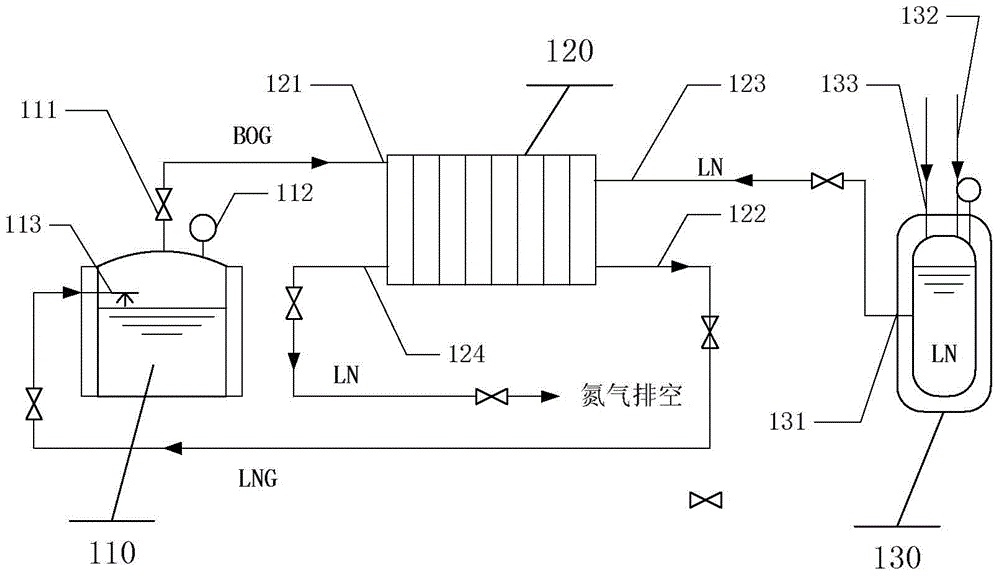
[0015] Such as figure 1 As shown, the device in this embodiment includes an LNG storage tank 110 , a condensation recovery device 120 , and a nitrogen storage tank 130 . Both the LNG storage tank 110 and the liquid nitrogen storage tank 130 are equipped with pressure detection device pressure gauges, and the inlet and outlet pipelines of the LNG storage tank 110, the condensate recovery device 120 and the nitrogen storage tank 130 are all equipped with check valves to control the flow direction of the fluid. . The pressure of the storage tank 110 increases with the continuous gasification of LNG. When the pressure is higher than the set value, the control system opens the one-way valve 111 at the outlet of the LNG storage tank 110, so that the BOG...


PUM


Abstract

The invention discloses a boil-off gas (BOG) recovering method, comprising a liquefied natural gas (LNG) storage tank, a double-row micro-channel harmonica-shaped tube condensation recovery device, a liquid nitrogen storage tank, an automatic control system and a plurality of auxiliary devices. In a recovering process, a compressor and a low-temperature pump are not utilized, and the self pressure of BOG gas and nitrogen is taken as a driving force of a fluid flowing in a pipeline. A BOG outlet of the LNG storage tank is directly connected with a BOG inlet receiver of the double-row micro-channel harmonica-shaped tube condensation recovery device through a pipeline, an outlet for the recovered LNG liquid is connected with the LNG storage tank through a pipeline, and the pipeline of the LNG storage tank is provided with a valve and a pressure detector; an outlet of the liquid nitrogen storage tank is connected with a liquid nitrogen inlet of the double-row micro-channel harmonica-shaped tube condensation recovery device through a pipeline, a nitrogen outlet of the condensation recovery device is divided into two paths, one path is directly connected with air, the other path is connected with the nitrogen inlet of the liquid nitrogen storage tank, and the pipeline of the liquid nitrogen storage tank is provided with a valve and a pressure detector.

Description

technical field [0001] The patent of the present invention relates to a method and device for recovering BOG, which is a new method and device for recovering BOG gas in industrial production, gas filling stations, LNG-powered ships, etc. Background technique [0002] With the continuous advancement and deepening of my country's energy conservation and emission reduction, LNG, as a gaseous clean energy with large reserves, high combustion calorific value and broad application prospects, is gradually becoming a substitute for liquid fuels such as gasoline and diesel. The main component of LNG is methane, which is in a gaseous state at normal temperature and pressure. However, in the process of storage, transportation and sales, it is necessary to liquefy the gaseous natural gas at normal temperature and pressure at 0.1MPa and -163°C, and it is used to store LNG. The tank must be insulated from external heat as much as possible to avoid re-gasification of the liquefied natural ...

Claims


Application Information

Patent Timeline
Patent Type & Authority Applications(China)
IPC IPC(8): F17C13/00F28B1/02
Inventor 凌祥刘冬稔陈伟
Owner 溧阳德维透平机械有限公司
Why Eureka
Try Eureka