Metasurface polarization regulator

A metasurface, polarization technology, applied in instruments, nonlinear optics, optics, etc., can solve the problems of not total reflection, signal loss, etc.

Active Publication Date: 2016-04-20
SHANGHAI INST OF TECHNICAL PHYSICS - CHINESE ACAD OF SCI
View PDF5 Cites 21 Cited by
  • Summary
  • Abstract
  • Description
  • Claims
  • Application Information

AI Technical Summary

Problems solved by technology

These methods have their own characteristics, but a common disadvantage is that these systems are not total reflection (or total transmission), so there is always a problem of signal loss during the application process.
Moreover, due to the li...

Method used


Image

  • Metasurface polarization regulator
  • Metasurface polarization regulator
  • Metasurface polarization regulator

Examples


Embodiment 1

[0023] Example 1. Metasurface Polarization Modulating Quarter Waveplate

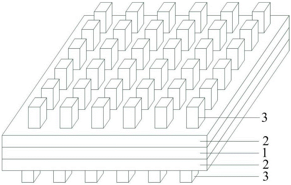
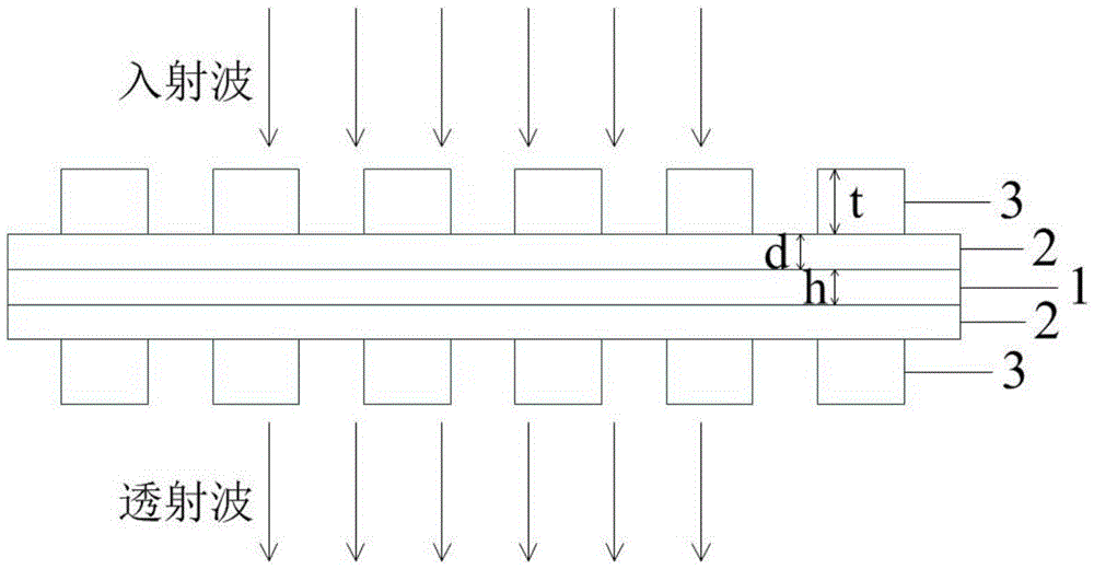
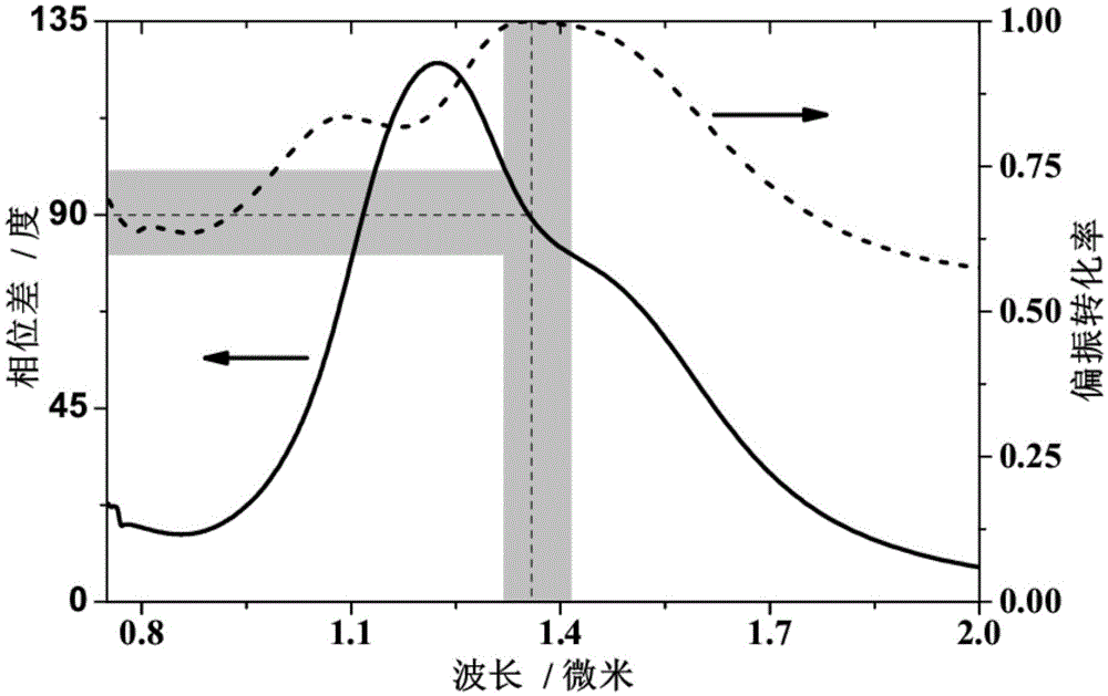
[0024] like figure 1 and figure 2 In the shown metasurface polarization modulator, the material of the intermediate metal layer (1) is silver (Ag), and its thickness is h=20nm. The upper and lower insulating dielectric layers (2) are made of the same material, which is aluminum oxide (Al 2 o 3 ), the thickness of which is d=25nm. The top and bottom microstructure layer (3) materials are the same as the middle metal thin film layer (1), which are metal silver (Ag) particles, which are periodically attached to the insulating medium layer (2) with a thickness of t=60nm, The microstructure unit period is 370nm. A wave plate is composed of several unit periodic structure arrays, such as figure 1 As shown, an array of 6×6 cell structures. The required phase difference can be obtained by adjusting the length and width of the top and bottom (3) metal microstructures Here we design the metasurface polar...

Embodiment 2

[0025] Embodiment 2. Metasurface polarization control half-wave plate

[0026] The metasurface polarization modulator realizes the function of half-wave plate, that is, it is required to realize the phase difference of the transmitted components in x direction and y direction in a certain band or frequency point And have a higher polarization conversion rate PCR hwp , where the polarization conversion rate is defined as PCR hpw =|t s-p | 2 / (|t s-p | 2 +|t s-s | 2 ), where t s-s , t s-p is the transmission coefficient, which respectively characterizes the ability of the s-polarized incident wave to keep the polarization state unchanged and transform the p-polarized transmitted wave after passing through the wave plate. Except that the length and width of the top and bottom metal microstructures are 190 nm and 130 nm, respectively, other structural parameters are exactly the same as those in Example 1. Figure 4 The phase difference of the x and y polarization transm...


PUM

PropertyMeasurementUnit
Thicknessaaaaaaaaaa
Thicknessaaaaaaaaaa
Thicknessaaaaaaaaaa

Abstract

The invention discloses a metasurface polarization regulator. The metasurface polarization regulator is composed of five structural layers. The top layer and the bottom layer are period metal micro-structure layers, the middle layer is a metal film layer, and the top layer, the bottom layer and the middle metal layer are separated by the insulating medium layers. The regulator works in a near infrared band, and the whole thickness of a system is far smaller than the working wavelength; the transmission rate of normal incidence electromagnetic waves is higher than 80%; as geometric parameters of the structure and the physical performances of relative materials are adjusted, the whole phase interval of 0-360 degrees can be covered with the phase difference between transmitted waves of an x component and transmitted waves of a y component, and therefore free adjustment of the polarization state of the electromagnetic waves can be achieved; for example, the transmission polarization state of electromagnetic waves transmitted through linear polarization can be transformed into the circular polarization state, the elliptical polarization state or the linear polarization state or even the complete polarization inversion state.

Description

technical field [0001] The invention relates to the technical field of optical devices, in particular to a metasurface polarization regulating device. Background technique [0002] Transverse wave (polarization), as one of the basic characteristics of light, affects and determines the properties of light and its applications in various aspects to a great extent. In order to detect the polarization state of light waves, we often need to use "optical polarization devices" to determine their polarization categories. In various optical instruments, in order to obtain the desired polarization state, we often need to realize the conversion between different polarization states. The application requirements of polarization devices used to detect, select or convert the polarization state of light / electromagnetic waves are becoming wider and wider, and the requirements for device performance are also getting higher and higher. Not only do devices require high efficiency, but they ar...

Claims


Application Information

Patent Timeline
IPC IPC(8): G02F1/01
CPCG02F1/0136
Inventor 郝加明李虎李志伟许昊俞伟伟杨名戴宁
Owner SHANGHAI INST OF TECHNICAL PHYSICS - CHINESE ACAD OF SCI
Why Eureka
Try Eureka