A plc-based continuous rolling transmission monitoring system and its monitoring method

A technology of monitoring system and monitoring unit, which is applied in the field of steel rolling in steel mills, can solve the problems of reducing the PLC module CPU control module of the main station, etc., and achieve the effects of improving scalability, convenient viewing and unified management, and improving stability and reliability

Active Publication Date: 2018-02-06
NANYANG HANYE SPECIAL STEEL CO LTD
View PDF8 Cites 0 Cited by
  • Summary
  • Abstract
  • Description
  • Claims
  • Application Information

AI Technical Summary

Problems solved by technology

Application number: 201310669221.3 patent for invention, which discloses a PLC control system, including a remote I / O module and a PLC master module. The remote I / O module is a VersaMax remote I / O module. Under the premise that the original Genius remote I / O module is replaced with the new VersaMax remote I / O module, the GeniusBus communication method is mainly used to exchange data with the GE90-30PLC module to realize mutual communication with each other. This control system can not only reduce The number of CPU control modules used in the main station PLC module also greatly saves the use of control cables, reduces costs and manual maintenance, makes up for the defects of the old generation of remote I / O modules that are not produced, and facilitates the unification of spare parts Ordering and replacement, but the main purpose of the invention is to reduce the number of equipment and cables used, thereby achieving the purpose of reducing costs and labor maintenance. There is no improvement for the control system and monitoring method of the rolling and continuous rolling transmission system; the application number is: The utility model patent of 201320111098.9 discloses an electrical monitoring system for the main electrical room of a rolling mill, including a programmable controller for the machine unit, a programmable controller for the vertical roller, a programmable controller for the oil depot, a programmable controller for the hydraulic station, and a programmable controller for bearing pad monitoring The switches are respectively connected to the switch, and the output of the switch is connected to the computer in the main control room. This utility model adopts the network technology based on Profibus and the Internet to implement networking with each programmable controller PLC. It is fast and effective, easy to operate, safe, environmentally friendly, The feature of wide application can play the role of analyzing the hidden dangers of the equipment according to the historical trend and troubleshooting the fault point, and this utility model can dynamically understand the equipment information and the state of the equipment chain signal, analyze the hidden dangers of the equipment, solve the equipment failure in time, reduce During unplanned shutdowns, production runs smoothly and energy is saved. However, this utility model only realizes field-level monitoring, and does not realize the integrated monitoring of the entire system, and the operating data of the system is not uploaded to the server for safe and reliable storage.

Method used


Image

  • A plc-based continuous rolling transmission monitoring system and its monitoring method
  • A plc-based continuous rolling transmission monitoring system and its monitoring method
  • A plc-based continuous rolling transmission monitoring system and its monitoring method

Examples


Embodiment 1

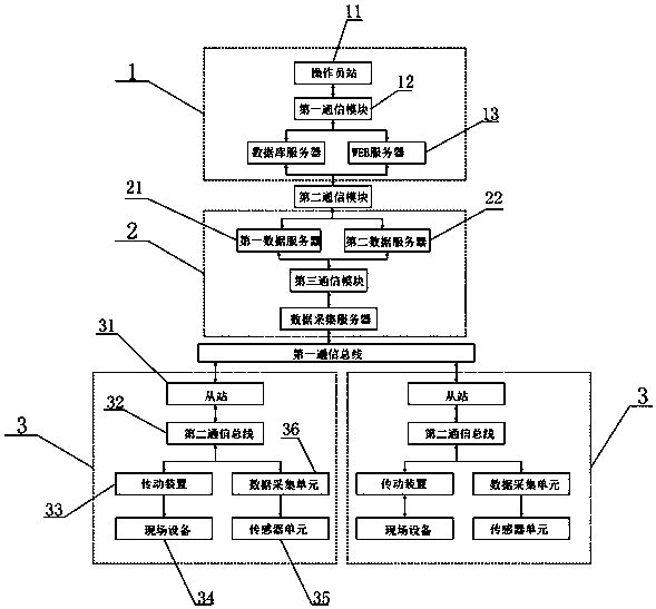
[0039] Such as figure 1 As shown, the present invention includes an upper monitoring unit 1, an intermediate network unit 2 and a plurality of on-site monitoring units 3; the upper monitoring unit 1 communicates with the intermediate network unit 2 through the second communication module, and the intermediate network unit 2 communicates through the first communication The bus communicates with the on-site monitoring unit 3, and the number of on-site monitoring units 3 in this embodiment is two.

[0040] The upper monitoring unit 1 includes an operator station 11, a database server and a WEB server 13. The operator station 11 adopts an industrial computer, and monitoring configuration software is installed in the industrial computer. The industrial computer accesses the data server and the WEB server 13 through the first communication module 12 , can read the data in the data server and the WEB server 13, and the first communication module 12 adopts a switch.

[0041] The inte...

Embodiment 2

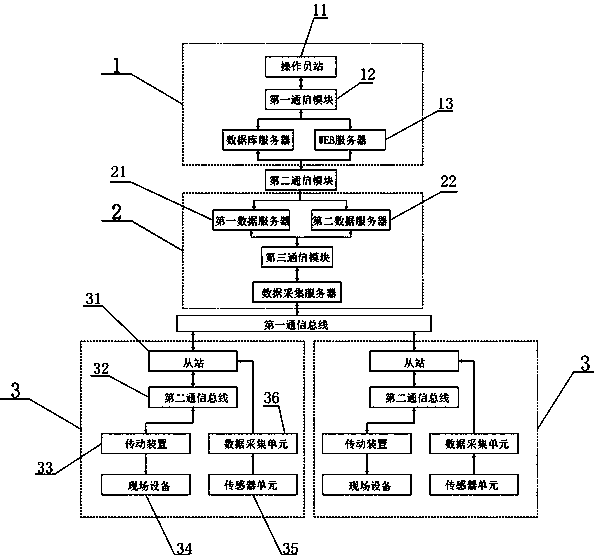
[0058] The difference between this embodiment and embodiment 1 is that, as figure 2 As shown, the data acquisition unit 36 ​​communicates directly with the slave station 31, the data acquisition unit 36 ​​has an RS485 communication interface, and the data acquisition unit 36 ​​communicates with the slave station 31 through the RS485 bus.

Embodiment 3

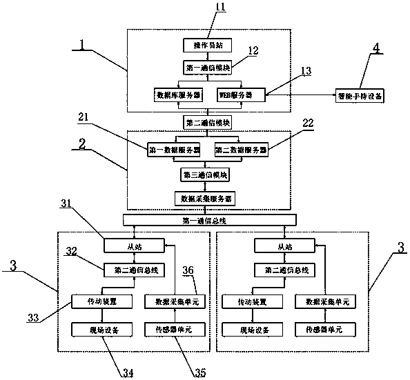
[0060] The difference between this embodiment and embodiment 2 is that, as image 3 As shown, the present invention also includes a smart handheld device 4, the smart handheld device 4 adopts a smart phone, and the smart phone is installed with an APP developed for this system, and accesses the WEB server 13 through the APP access Internet network, and the smart handheld device 4 can be used anytime, anywhere access the data in the WEB server 13, and keep abreast of the operating conditions of the system.


PUM


Abstract

The invention discloses a PLC-based continuous rolling transmission monitoring system and a monitoring method thereof, comprising an upper monitoring unit, an intermediate network unit and a plurality of on-site monitoring units, the upper monitoring unit communicates with the intermediate network through a second communication module The unit communicates, and the intermediate network unit communicates with the on-site monitoring unit through the first communication bus. The invention also discloses a PLC-based continuous rolling transmission monitoring system and its monitoring method. According to the control parameters of the unit And the operating parameters of the unit, the working status of the rolling unit is controlled through the PLC control transmission device, and the working status data of the rolling unit can be sent to the operator station in the upper monitoring unit through the network for monitoring. The control system and the monitoring system realized by the present invention have a three-level network structure, and data communication is realized through switches between each network structure, which can conveniently realize the hierarchical flow of monitoring information flow, and is suitable for the control needs of different managements.

Description

technical field [0001] The invention relates to the technical field of steel rolling in steel mills, in particular to a PLC-based continuous rolling transmission monitoring system and a monitoring method thereof. Background technique [0002] Rolled steel products play a pivotal role in all walks of life in modernization, including housing, petrochemical, electromechanical, automobile and other industries are inseparable from rolled steel products. The main production process of contemporary steel rolling technology is different from the old ones in the past, and the products are directly rolled into shape. In the past, the control method was manual analog quantity control, and the controller adjusted the input speed setting of the speed control device; if the system detects that the device is in a fault state, it will stop directly, and the operator and maintenance personnel cannot query the fault information; the transmission device and The communication between the conso...

Claims


Application Information

Patent Timeline
Patent Type & Authority Patents(China)
IPC IPC(8): G05B19/418
CPCY02P90/02
Inventor 朱书成许少普薛礼峰屠红选康文举杨春刘彦顺李荷李士群
Owner NANYANG HANYE SPECIAL STEEL CO LTD
Why Eureka
Try Eureka