
Band-gap reference starting circuit with super-low leakage current

A leakage current and reference technology, applied in the direction of adjusting electrical variables, control/regulating systems, instruments, etc., can solve the problems of incomplete matching of triodes, output reference voltage imbalance, increase layout area, etc., to achieve obvious shutdown effect and start-up. The effect of fast speed and saving chip area

Active Publication Date: 2016-04-20
南京集成电路设计服务产业创新中心有限公司
View PDF5 Cites 8 Cited by
  • Summary
  • Abstract
  • Description
  • Claims
  • Application Information

AI Technical Summary

Problems solved by technology

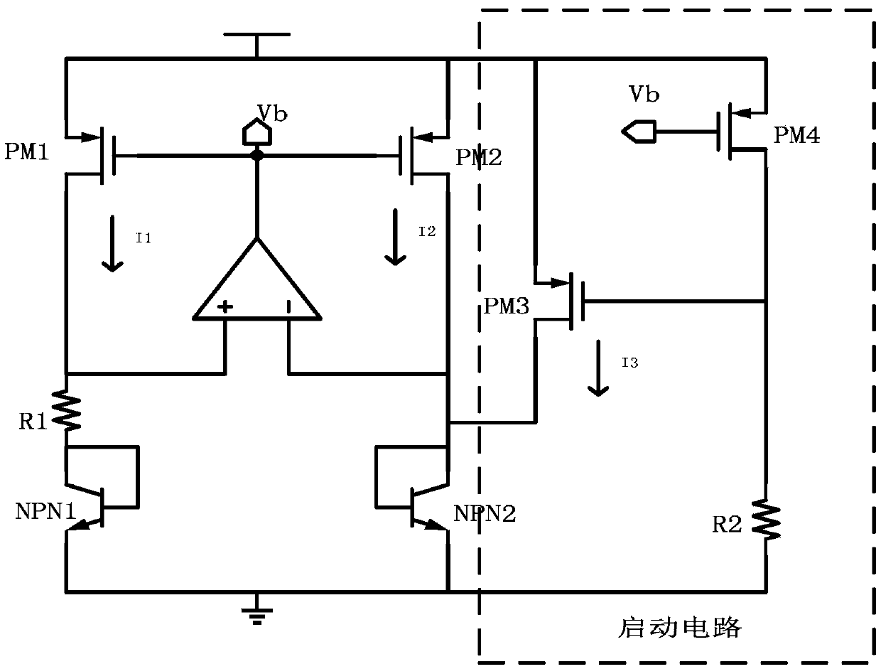
[0003] In most start-up circuits, as attached figure 1 , the PMOS device is mostly used as the start-up switch, and the resistance is used as the current mirror of the load. The drain voltage of the PMOS is the base-emitter voltage of the triode, and the source voltage is the power supply. ) The leakage current I3 is large, and this leakage current will divert part of the triode current, so that the currents I1 and I2 of the two triodes cannot be completely matched. When the power consumption of the bandgap reference itself is very low, for example, I1 and I2 themselves are only tens of microamperes , and when the current of I3 reaches tens of nanoamperes, the current mismatch will cause the output reference voltage to be out of adjustment, and if the resistance is used as the load, the formation of the layout will increase the layout area

Method used


Image

  • Band-gap reference starting circuit with super-low leakage current
  • Band-gap reference starting circuit with super-low leakage current
  • Band-gap reference starting circuit with super-low leakage current

Examples


Embodiment Construction

[0015] The present invention will be further described below in conjunction with the accompanying drawings.

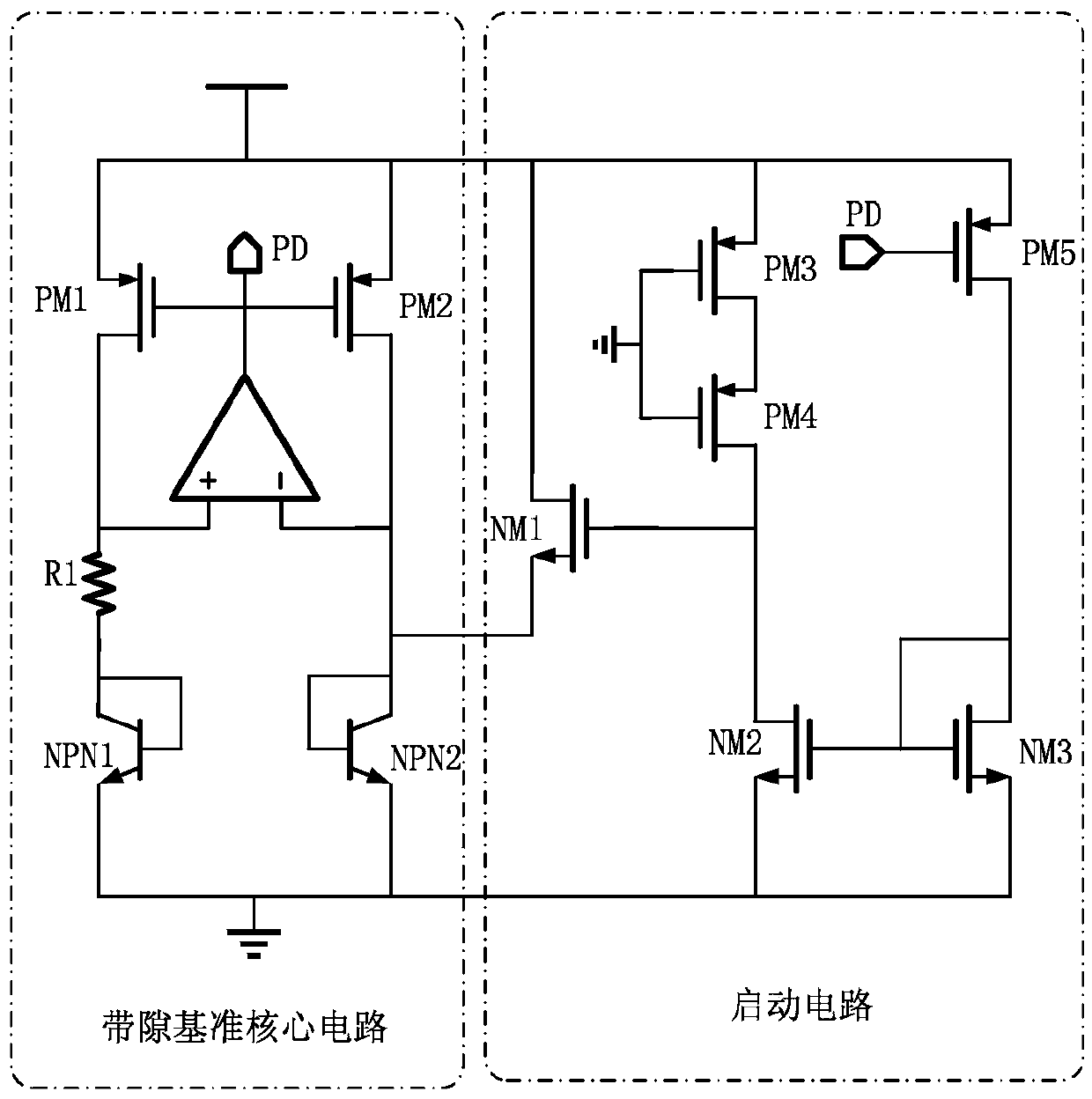
[0016] Such as figure 1 Shown is a bandgap reference start-up circuit with extremely low leakage current, including a high aspect ratio PMOS transistor, a current mirror and an NMOS switch. The high aspect ratio PMOS transistor is used as a resistor, and the NMOS switch is connected to the input terminal of the bandgap reference core circuit , the current mirror is connected to the output terminal of the bandgap reference core circuit; the high aspect ratio PMOS transistor is a PMOS transistor with an aspect ratio greater than or equal to 10:1.

[0017] The high aspect ratio PMOS transistor includes a third PMOS transistor PM3, the gate of the third PMOS transistor PM3 is grounded, the source is connected to the power supply voltage VDD, and the drain is connected to the drain of the second NMOS transistor NM2.

[0018] The current mirror includes a second NMOS transi...


PUM


Abstract

The invention discloses a band-gap reference starting circuit with super-low leakage current, which comprises a PMOS (P-channel Metal Oxide Semiconductor) pipe at high length-width ratio, a current mirror and an NMOS (N-channel Metal Oxide Semiconductor) switch, wherein the PMOS pipe at the high length-width ratio is used as a resistor, the NMOS switch is connected with an input end of a band-gap reference core circuit, and the current mirror is connected with an output end of the band-gap reference core circuit. According to the band-gap reference starting circuit, the NMOS switch is adopted, so that the starting speed is higher than that of the PMOS switch; after the band-gap reference core circuit normally operates, the NMOS switch is turned off, the gate source voltage of the NMOS switch is the negative voltage, so that the turn-off effect is more obvious, leakage current at any process corner and any temperature can be lower than the Pian grade, the affection of the leakage current on reference source current can be omitted, other branches of the starting circuit are still in a conducting state, however, the static current of the starting circuit is very small; in addition, the PMOS pipe resistor replaces a conventional passive resistor, and therefore, the area of a chip is saved.

Description

technical field [0001] The invention relates to a bandgap reference starting circuit with extremely low leakage current, which belongs to the integrated circuit technology. Background technique [0002] In analog circuits and mixed-signal circuits, the bandgap reference circuit is one of the very important units. Its basic function is to provide a reference voltage that is almost independent of the chip input voltage and temperature for use by other functional modules. With the development of integrated circuits and the complexity of SOC systems, the requirements for power consumption, offset voltage and startup speed of bandgap references are getting higher and higher. A very important issue in the power-independent bias circuit in the bandgap reference circuit is the existence of "degenerate" bias points, that is, there are two balanced operating points in the bandgap reference circuit, one of which is zero, and can be infinitely One remains off, and the other is the norm...

Claims


Application Information

Patent Timeline
Patent Type & Authority Applications(China)
IPC IPC(8): G05F1/56
CPCG05F1/56
Inventor 吴建辉孙杰傅娟李红
Owner 南京集成电路设计服务产业创新中心有限公司
Learn More