A stacked radio frequency power amplifier

A technology of radio frequency power and stacking structure, applied in power amplifiers, high frequency amplifiers, amplifiers, etc., can solve problems such as transistor breakdown and low output power, and achieve increased output voltage swing, improved linearity, and improved withstand voltage Effect

Inactive Publication Date: 2019-01-25
臻智微芯(广州)技术有限公司
View PDF4 Cites 0 Cited by
  • Summary
  • Abstract
  • Description
  • Claims
  • Application Information

AI Technical Summary

Problems solved by technology

As the power of the input signal increases, the output voltage signal also becomes larger, which will make the transistor on the uppermost layer of the structure the first to have a breakdown problem
In addition, since the output impedance of the two transistors in the cascode structure is not optimal impedance, the output power is small

Method used


Image

  • A stacked radio frequency power amplifier
  • A stacked radio frequency power amplifier
  • A stacked radio frequency power amplifier

Examples


Embodiment Construction

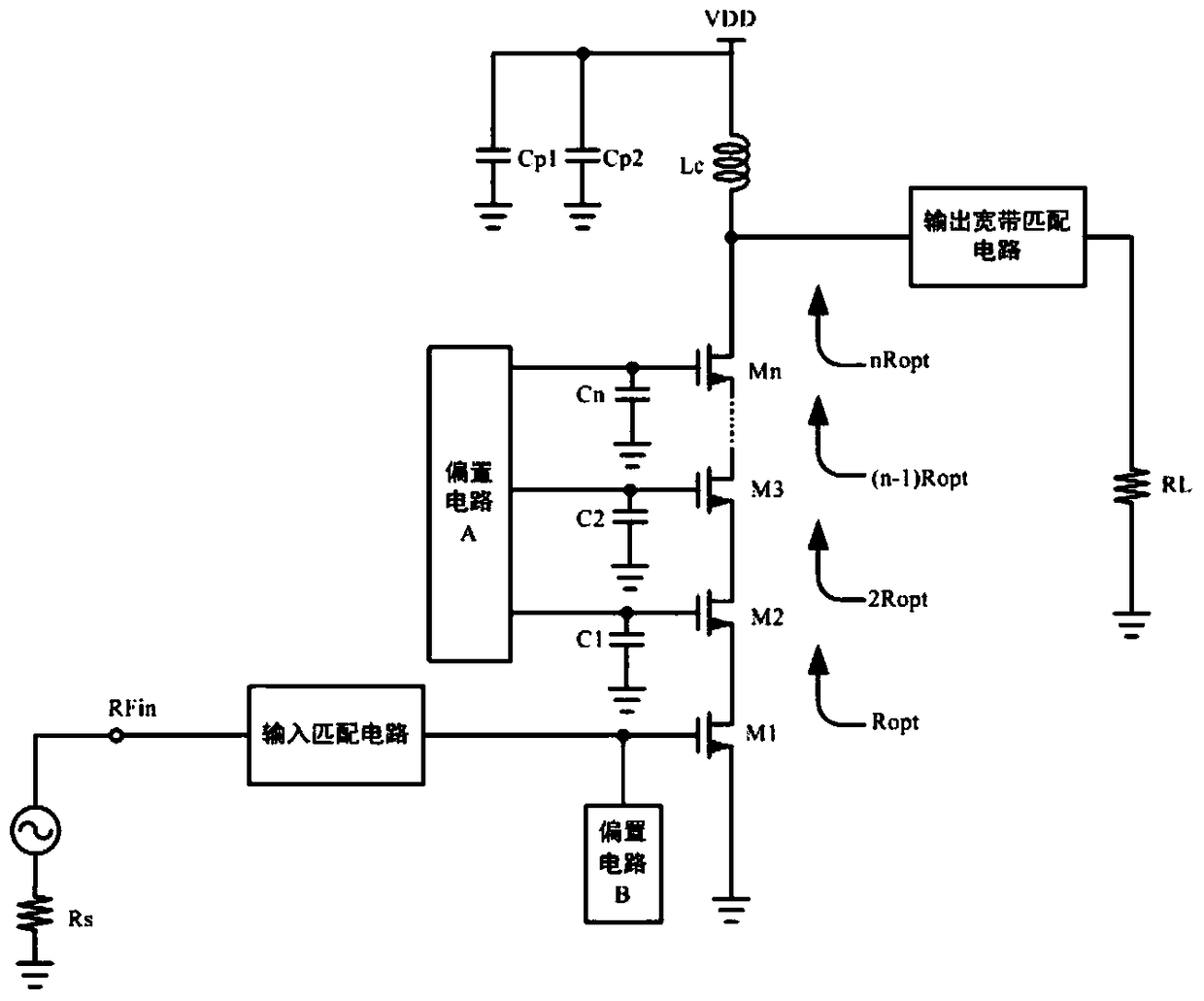
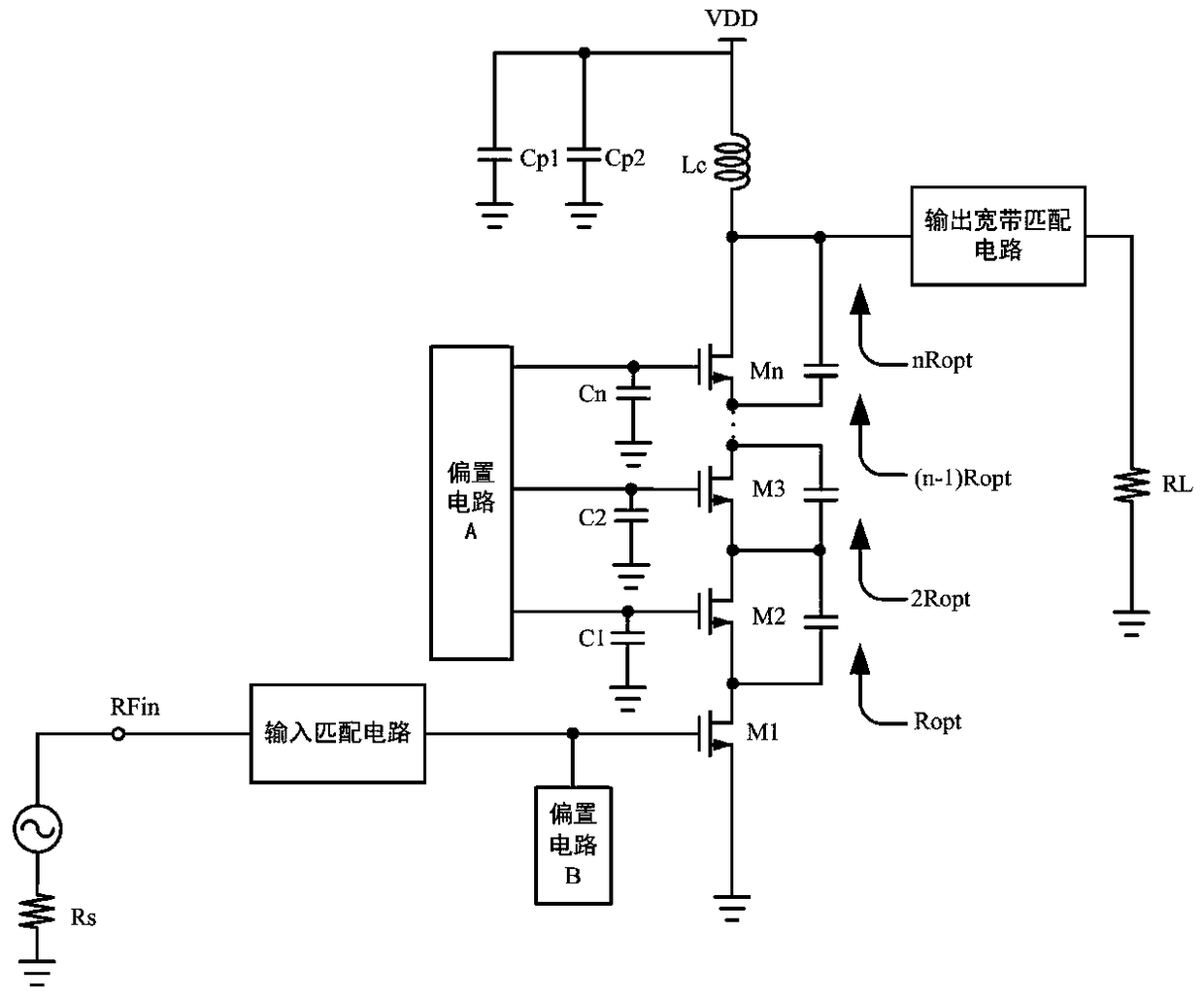
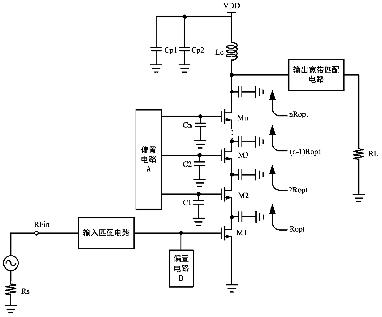
[0030] A preferred embodiment of the present invention, a kind of radio frequency power amplifier of stacking structure, such as Figure 5 As shown, the RF power amplifier includes an input matching circuit 201, an output broadband matching circuit 214, a bias circuit A namely 203, a bias circuit B namely 202, and four transistors (ie, M1 to M4, 204 to 207 in the figure) A power amplifying circuit in which the drain and the source are connected and stacked; wherein, the radio frequency signal source RFin is connected to the gate of the bottom transistor 204 of the power amplifying circuit through the input matching circuit 201, and the bias circuit B is connected to 202 The gate of the transistor 204, the source of the transistor 204 is grounded; the bias circuit A, namely 203, is connected to the gates of the remaining transistors (205 to 207) of the power amplifier circuit, and the gates of the transistors 205 to 207 are The gate is connected to the ground through the gate c...


PUM


Abstract

The invention discloses a radio-frequency power amplifier with a stack structure. The radio-frequency power amplifier comprises an input matching circuit, an output broadband matching circuit, a biasing circuit A, a biasing circuit B and a power amplification circuit, and the power amplification circuit is formed by stacking of at least two transistors with drains and sources connected. A radio-frequency signal source is connected with a grid electrode of the bottom transistor of the power amplification circuit through the input matching circuit, the biasing circuit B is connected with the grid electrode of the bottom transistor, and the source of the bottom transistor is grounded. The drain of the top transistor of the power amplification circuit is connected with a load through the output broadband matching circuit. Integral linearity, output voltage swing, operation bandwidth, power efficiency, power gain and maximum output power of the radio-frequency power amplifier are increased, and excellent second harmonic inhibition effects are achieved.

Description

technical field [0001] The invention relates to a power amplifier, in particular to a radio frequency power amplifier. Background technique [0002] The RF power amplifier is an important part of the modern wireless communication system, which can amplify the power of the RF signal with very small power without distortion, and then radiate it through the antenna. [0003] As the functional modules of portable devices and the modulation methods of modern communication systems become more and more complex, for example, in order to meet the needs of different users, wireless mobile phones generally support two or more It is required that modern communication systems adopt modulation methods such as QPSK, which requires that power amplifiers used in new generation communication systems must have high power efficiency, linearity and bandwidth. [0004] In addition, as the functional modules of portable devices become more and more complex, integrating each functional module on o...

Claims


Application Information

Patent Timeline
Patent Type & Authority Patents(China)
IPC IPC(8): H03F1/32H03F1/42H03F1/52H03F1/56H03F3/19H03F3/21H03F3/24
CPCH03F1/3205H03F1/42H03F1/523H03F1/56H03F3/19H03F3/21H03F3/245
Inventor 林俊明章国豪张志浩余凯黄亮李嘉进陈锦涛
Owner 臻智微芯(广州)技术有限公司
Why Eureka
Try Eureka