Machining head, laser machining tool, and method for replacing a protective glass in the machining head

A technology of laser processing machine and protective glass, which can be used in metal processing machinery parts, metal processing, laser welding equipment, etc., and can solve problems such as pollution.

Active Publication Date: 2016-04-20
TRUMPF WERKZEUGMASCHINEN GMBH & CO KG
View PDF14 Cites 6 Cited by
  • Summary
  • Abstract
  • Description
  • Claims
  • Application Information

AI Technical Summary

Problems solved by technology

Since the processing head and thus the protective glass box are usually contaminated on the outside, this contamination can reach the new protective glass or the inner side of the box

Method used


Image

  • Machining head, laser machining tool, and method for replacing a protective glass in the machining head
  • Machining head, laser machining tool, and method for replacing a protective glass in the machining head
  • Machining head, laser machining tool, and method for replacing a protective glass in the machining head

Examples


Embodiment Construction

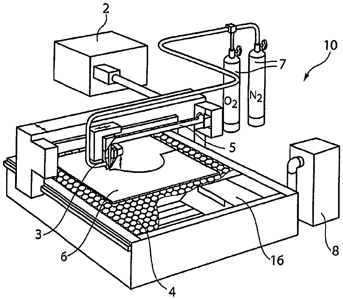
[0043] figure 1 The processing machine 10 is shown three-dimensionally, and the figure shows the structure of a laser cutting machine as an example of a laser processing machine. Other embodiments are eg laser welding machines or combined stamping / laser cutting machines. Such a processing machine 10 has a carbon dioxide laser or solid-state laser as laser beam generator 2 , a laser processing head or processing head 3 , and a workpiece support 4 . A workpiece 6 is arranged on the workpiece carrier 4 . Laser beam 5 is generated by laser 2 . The laser beam 5 is guided to the processing head 3 by means of a deflection mirror (not shown) of the carbon dioxide laser or by means of an optical cable (not shown) of the solid-state laser. The laser beam 5 is directed towards the workpiece 6 by means of focusing optics arranged in the processing head 3 . The processing machine 10 is also supplied with cutting gases 7 (for example oxygen and nitrogen). Alternatively or additionally,...


PUM


Abstract

The invention relates to a machining head (3) for a laser machining tool for machining a workpiece by means of a laser beam, which is focused by means of a focusing optical unit arranged in a first housing part (12) and exits the machining head (3) through protective glass (29) arranged after the focusing optical unit in a beam propagation direction, wherein the protective glass (29) is arranged in a second housing part (14), which is detachably fastened to the first housing part (12) and which remains connected to the first housing part (12) by means of a coupling element (31) after the detachment from the first housing part (12) and which can be at least translated or pivoted with respect to the first housing part (12).

Description

technical field [0001] The invention relates to a processing head of a laser processing machine for processing workpieces by means of a laser beam, a laser processing machine, and a method for replacing a protective glass in a processing head. Background technique [0002] It is known to process workpieces, in particular plate-shaped workpieces, by means of laser beams. The laser beam is guided through the processing head, focused by means of focusing optics and directed towards the workpiece. These optical components are protected against contamination by splashes or dense fumes by a protective glass, which is arranged in the workpiece-side end of the processing head. Depending on the parameters of the machining process performed, the protective glass becomes contaminated more or less quickly and must be replaced after a certain period of time. [0003] In order to expedite this replacement of the cover glass, a cassette has been designed as a holder for the cover glass, ...

Claims


Application Information

Patent Timeline
Patent Type & Authority Applications(China)
IPC IPC(8): B23K37/02B23K26/08B23K26/14B23Q3/155G02B7/14G03B17/14
CPCB23K37/0235B23K26/0876B23K26/1476B23K26/1482B23K26/1494B23K2101/18
Inventor G·布罗格哈默
Owner TRUMPF WERKZEUGMASCHINEN GMBH & CO KG
Why Eureka
Try Eureka