Manufacturing technique and equipment for high-performance composite roller shaft

A manufacturing process and compound roll technology, which is applied in the field of metal pressure processing, can solve the problems of complex production process, high power consumption, low efficiency, etc., and achieve the effect of overcoming tissue segregation, high density, and favorable compounding

Active Publication Date: 2016-04-27
丹阳恒庆复合材料科技有限公司
View PDF8 Cites 10 Cited by
  • Summary
  • Abstract
  • Description
  • Claims
  • Application Information

AI Technical Summary

Problems solved by technology

[0023] The purpose of the present invention is to address the deficiencies of the existing technology, to propose a new high-performance composite roller shaft manufacturing process and equipment with simple production process, low equipment investment, high production efficiency, low cost and good performance, and simplify the composite roller shaft man

Method used


Image

  • Manufacturing technique and equipment for high-performance composite roller shaft
  • Manufacturing technique and equipment for high-performance composite roller shaft
  • Manufacturing technique and equipment for high-performance composite roller shaft

Examples


Example Embodiment

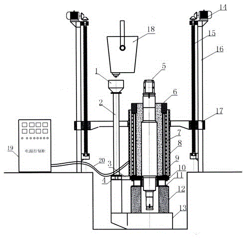
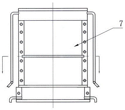
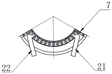
[0047] Embodiment 1: in figure 1 , figure 2 , image 3 , Figure 4 , Figure 5 Among them, the equipment has a gantry-type regional directional solidification lifting device 16, a lifting platform 17 is installed on the gantry-type regional directional solidification lifting device 6, an electromagnetic induction heater 8 is installed on the lifting platform 17, and the lifting motor 14 rotates and lifts The screw 15 or hydraulic equipment drives the lifting table 17 to move up and down at the set speed, and the electromagnetic induction power control cabinet 19 is installed on the side of the directional solidification lifting equipment 16 in the gantry type area. The two output ends of the electromagnetic induction power control cabinet 19 are cooled by water. The cable 20 is connected to the two ends of the electromagnetic induction heater 8, and there is a base bracket at the bottom of the directional solidification lifting device 16 in the gantry type area, and a supp...

Example Embodiment

[0050] Example 2: In figure 1 , figure 2 , image 3 , Figure 4 , Figure 5 Among them, the equipment has a gantry-type regional directional solidification lifting device 16, a lifting platform 17 is installed on the gantry-type regional directional solidification lifting device 6, an electromagnetic induction heater 8 is installed on the lifting platform 17, and the lifting motor 14 rotates and lifts The screw 15 or hydraulic equipment drives the lifting table 17 to move up and down at the set speed, and the electromagnetic induction power control cabinet 19 is installed on the side of the directional solidification lifting equipment 16 in the gantry type area. The two output ends of the electromagnetic induction power control cabinet 19 are cooled by water. The cable 20 is connected to the two ends of the electromagnetic induction heater 8, and there is a base bracket at the bottom of the directional solidification lifting device 16 in the gantry type area, and a support...

Example Embodiment

[0053] Example 3: In figure 1 , figure 2 , image 3 , Figure 4 , Figure 5 Among them, the equipment has a gantry-type regional directional solidification lifting device 16, a lifting platform 17 is installed on the gantry-type regional directional solidification lifting device 6, an electromagnetic induction heater 8 is installed on the lifting platform 17, and the lifting motor 14 rotates and lifts The screw 15 or hydraulic equipment drives the lifting table 17 to move up and down at the set speed, and the electromagnetic induction power control cabinet 19 is installed on the side of the directional solidification lifting equipment 16 in the gantry type area. The two output ends of the electromagnetic induction power control cabinet 19 are cooled by water. The cable 20 is connected to the two ends of the electromagnetic induction heater 8, and there is a base bracket at the bottom of the directional solidification lifting device 16 in the gantry type area, and a support...


PUM


Abstract

The invention discloses a manufacturing technique and equipment for a high-performance composite roller shaft. The manufacturing technique comprises the steps that a mandril installed in a combined water-cooling crystallizer is integrally heated to 840-1100 DEG C through an induction heater; molten liquid of a working layer of the roller shaft is poured into the mandril, and then the mandril is continued to be heated for 10-50 minutes; a lifting device is stared so as to lift the heater at a certain speed for 5-15 minutes, and the heater is stopped in the position of a heat-insulating ring; and heating is continued for 10-50 minutes, feeding is conducted on a dead head, and after heating is stopped, cooling is conducted for 30 minutes to 24 hours through water. When the composite roller shaft is manufactured through the manufacturing technique, the number of controllable technological parameters is small, the interface of a composite layer is easy to control, the technique is simple, the efficiency is high, the power consumption is low, the cost is low, the composite layer is free of composition segregation, and the service life of the roller shaft is long; the defect of a centrifugation method that structure segregation is prone to occurring is overcome, and the problems of a CPC method and an ESR method that the production technique is complex, and the cost is high are solved.

Description

technical field [0001] The invention belongs to the technical field of metal pressure processing, and in particular relates to a high-performance composite roller shaft manufacturing process and equipment, which are suitable for manufacturing composite rollers in the steel rolling industry. Background technique [0002] Roller parts are widely used in metallurgy, mining, electric power, petrochemical, building materials and other fields. They are bulky and consumable key components of rolling deformation, crushing, grinding and supporting, conveying, guiding and other equipment. The annual consumption is more than 5 million tons, worth 10 million More than 100 million yuan. Shaft parts are the key components of equipment, and the annual consumption is hundreds of billions of yuan. The existing manufacturing process has problems such as high cost, low efficiency, poor quality, and short service life, resulting in huge waste and pollution. [0003] The roll is known as the "...

Claims


Application Information

Patent Timeline
IPC IPC(8): B22D11/049B22D19/16
Inventor 丁家伟丁刚耿德英鹿微微鹿策施孟达孔军
Owner 丹阳恒庆复合材料科技有限公司
Why Eureka
Try Eureka