Automatic steel pipe chamfering machine

A chamfering machine, fully automatic technology, applied in the field of steel pipe manufacturing, can solve the problems that the processing capacity of the chamfering machine cannot meet the requirements simultaneously, the structure and power of the chamfering machine need to be improved, and the cutting capacity of the chamfering machine is insufficient, etc., to achieve collection The method is convenient and reasonable, the effect of eliminating unsafe factors and perfect safety protection measures

Active Publication Date: 2017-11-28
SUNYO S&T CO LTD
View PDF7 Cites 1 Cited by
  • Summary
  • Abstract
  • Description
  • Claims
  • Application Information

AI Technical Summary

Problems solved by technology

At present, there are application requirements for steel pipes with a wall thickness of more than 50mm, but the processing capacity of the chamfering machine cannot meet the requirements at the same time. The main performance is that the cutting capacity of the chamfering machine is insufficient, and the structure and power of the chamfering machine need to be improved.
In terms of safety protection, when the chamfering machine cuts the pipe end, the iron filings are easy to fly out and hurt people. In general, the simple protection such as protective net cover or protective door can no longer meet the requirements of safety protection.

Method used


Image

  • Automatic steel pipe chamfering machine
  • Automatic steel pipe chamfering machine
  • Automatic steel pipe chamfering machine

Examples


Embodiment Construction

[0031] The specific embodiments of the present invention will be described below in conjunction with the drawings.

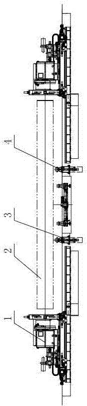
[0032] Such as figure 1 As shown, in the full-automatic steel pipe chamfering machine of this embodiment, in the actual application process, the steel pipe 2 is supported by the pipe carrier 4, and at the same time, the height position of the steel pipe 2 is adjusted by the support cylinder 3 inside the pipe carrier 4. The mobile cutting switchboard 1 is installed at each end.

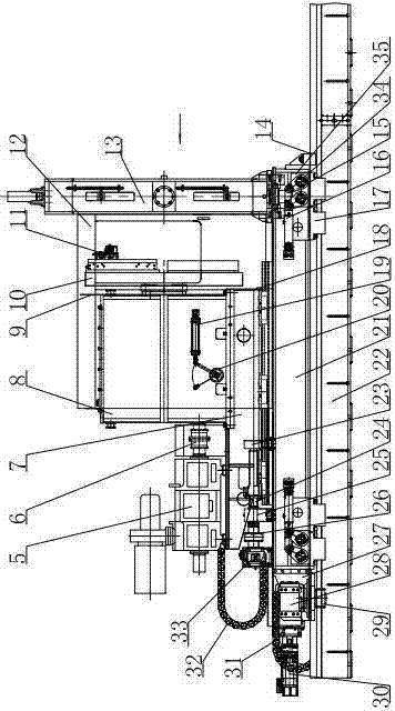
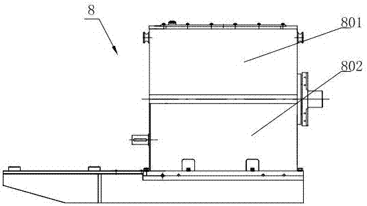
[0033] Such as figure 2 with image 3 As shown, the structure of the mobile cutting switchboard 1 is as follows: includes a base 22 on which a large carriage 21 is installed. Both ends of the large carriage 21 are respectively equipped with hook plates 17, which are driven by the hydraulic cylinder drive device. 22 Hook tightly; a base box 7 is installed on the large carriage 21 through a slide rail, and a bedside box 8 is installed on the base box 7 through fasteners. The bedside box 8 is a...


PUM


Abstract

A fully automatic steel pipe chamfering machine comprises a base (22). A large carrier plate (21) is mounted on the base (22), and is provided with a hook plate (17) respectively on two sides, the hook plates hooking tightly to the base. The large carrier plate is mounted with a base housing (7) by means of a sliding rail, and a headstock (8) is mounted on the base housing by means of a fastener. The headstock has a modular structure including an upper headstock member (801) and a lower headstock member (802), the lower headstock member is connected to the base housing, the upper headstock member is mounted on the lower headstock member, and a gear transmission mechanism is mounted in the lower headstock member. A primary motor (5) is mounted above the base housing at the lower portion of the headstock, an output end of the primary motor is connected to the gear transmission mechanism in the headstock by means of a first coupling (6). A cutter disk (10) is mounted on an outer side of the headstock, and a cutting device (11) is mounted on the cutter disk. A holder device (13) is further mounted at one end of the large carrier plate, a first drag chain (31) is mounted at one end of the large carrier plate, and a second drag chain (32) is mounted at a top portion of the first drag chain by means of a holder plate. The fully automatic steel pipe chamfering machine has a high level of automation, superior machining capability, and excellent safety and reliability.

Description

Technical field [0001] The invention relates to the technical field of steel pipe manufacturing, in particular to an automatic steel pipe chamfering machine applied to the manufacture of large-diameter straight seam and spiral submerged arc welded steel pipes. Background technique [0002] On the φ508-φ1422mm large-diameter straight seam, spiral submerged arc welded steel pipe production line, the chamfering machine is used to process the pipe end bevel and is one of the key equipment of the production line. For many years, the automation level and production efficiency of the chamfering machine are low. The end processing of the steel pipe depends on the manual control of the operator. The mold used for the steel pipe clamping needs to be replaced according to the specifications of the steel pipe. As the demand for large-diameter submerged arc welded pipes continues to increase, the range of steel pipe specifications is also expanding. At present, there are existing application...

Claims


Application Information

Patent Timeline
Patent Type & Authority Patents(China)
IPC IPC(8): B23D79/00B23Q11/00B23Q3/06B23Q1/25
CPCB23B5/16B23D79/00B23Q11/00
Inventor 张昊羽赵东吴正东顾亚李猛胡宜新吴哲
Owner SUNYO S&T CO LTD
Why Eureka
Try Eureka