High-speed truss manipulator

A technology of manipulators and trusses, applied in the field of truss manipulators, can solve the problems of large vibration, low alternating operation speed, and low guiding precision, so as to achieve high-efficiency work, avoid long-term waiting, and improve rigidity and strength.

Inactive Publication Date: 2016-04-27
SUZHOU KAILINJIE ROBOT CO LTD
View PDF13 Cites 28 Cited by
  • Summary
  • Abstract
  • Description
  • Claims
  • Application Information

AI Technical Summary

Problems solved by technology

[0002] The truss manipulator is a fully automatic industrial equipment based on the three-coordinate system of right angles X, Y, and Z, which can adjust the position of the workpiece or realize the trajectory movement of the workpiece. It controls the manipulator through the industrial controller to complete X, The joint movement between the Y and Z axes is used to realize a complete set of fully automatic operation processes. It is often used on large-scale processing equipment. The traditional truss manipulator is heavy in weight and has low guiding precision. The manipulator is prone to large vibrations during operation, resulting in The position accuracy of the manipulator is low, and the running speed is slow. Most of the manipulators are one or two manipulators flipped along the 180-degree direction to achieve alternate operation, which takes up a lot of space, and the alternating operation speed is low. Because of its large size and weight, the vibration amplitude of the manipulator is aggravated, and the movement of the manipulator It cannot stop immediately after it is in place, but only stops after swinging in situ for a certain period of time, resulting in low processing accuracy and low processing efficiency, which brings great troubles to actual production

Method used


Image

  • High-speed truss manipulator
  • High-speed truss manipulator
  • High-speed truss manipulator

Examples


Embodiment

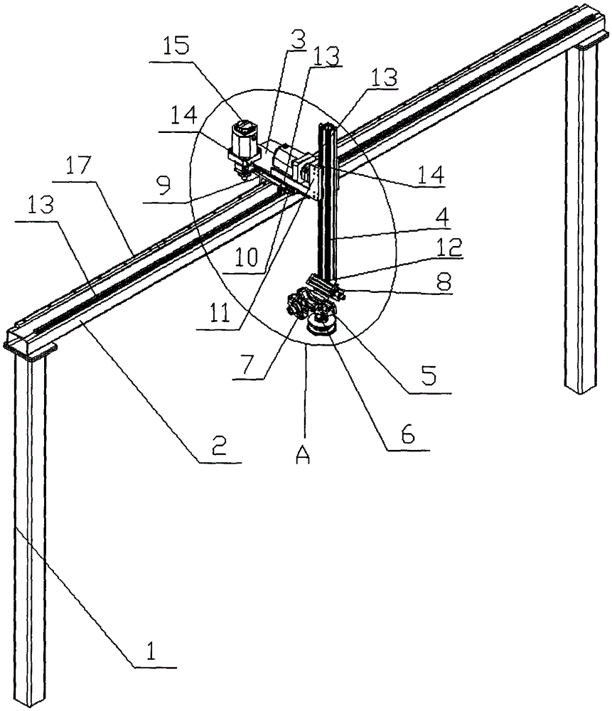
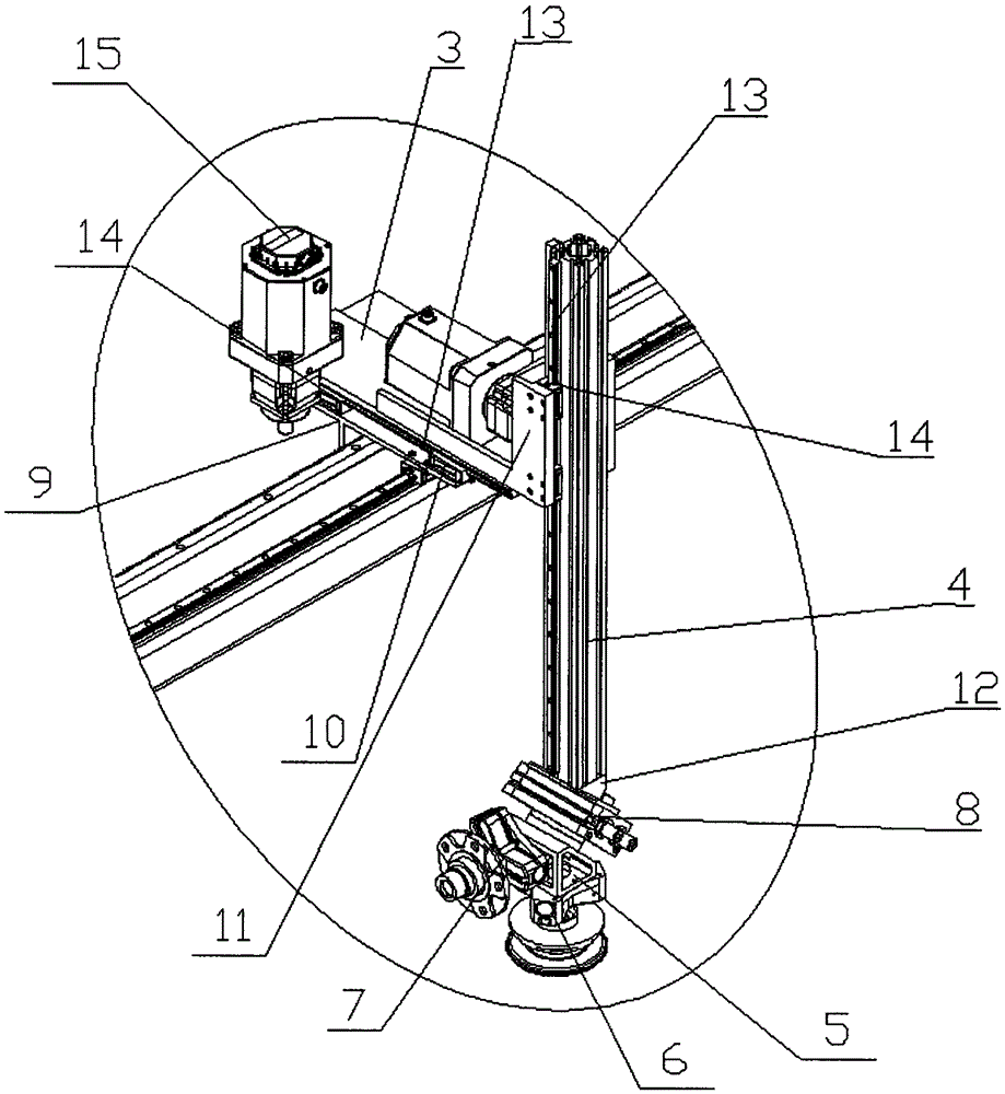
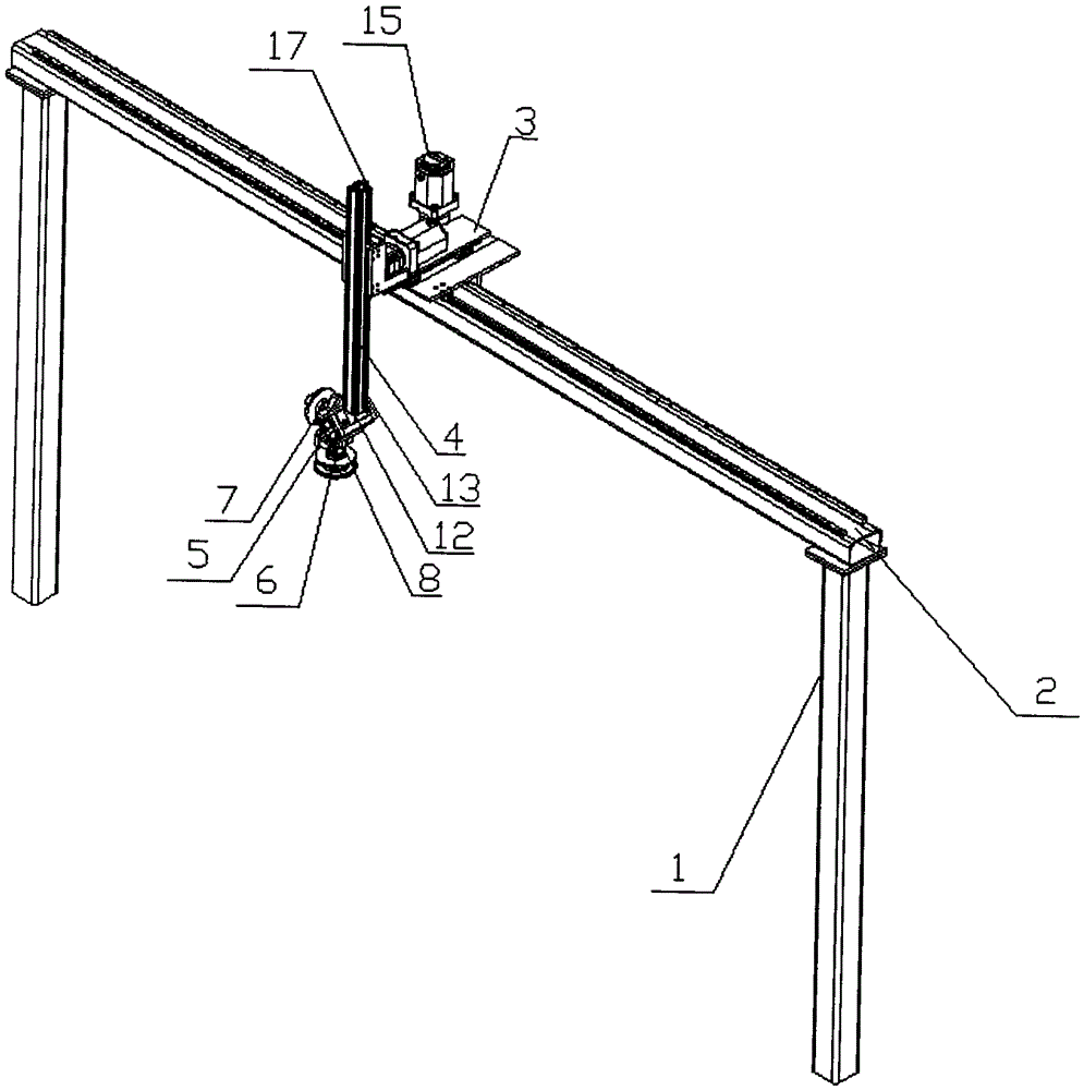
[0022] Embodiment: A high-speed truss manipulator, set three mutually perpendicular directions as X direction, Y direction and Z direction respectively, wherein Z direction is the vertical direction, including support frame 1, X direction track 2, Y direction track 3, Z-direction track 4, mechanical gripper mounting bracket 5, first and second mechanical grippers 6, 7, first, second and third drive devices, rotary drive device 8 and first, second and third sliders 9, 10 and 11 , the X-direction rail 2 is horizontally installed on the upper end of the support frame 1, the first slider 9 can slide and be positioned on the X-direction rail 2 along the extension direction of the X-direction rail 2, and the second slider 10 is fixedly installed on the first slider 9 Above, the Y-direction track 3 can be reciprocally slid along the Y direction and positioned on the second slider 10, the third slider 11 is fixedly installed on the Y-direction track 3, and the Z-direction track 4 can b...


PUM


Abstract

The invention discloses a high-speed truss manipulator. A first sliding block is arranged on an X-direction track on a supporting frame in a sliding mode; a Y-direction track is arranged on a second sliding block fixed to the first sliding block in a linearly reciprocated sliding mode; a Z-direction track is arranged on a third sliding block fixed to the Y-direction track in a longitudinally and linearly reciprocated sliding mode; a mechanical clamping jaw installation support is rotationally positioned at the lower end of the Z-direction track; an included angle of 135 degrees is formed between the axial direction of a rotary shaft of the mechanical clamping jaw installation support and the Z direction; first and second mechanical clamping jaws are symmetrically distributed on the two sides of the rotary shaft of the mechanical clamping jaw installation support; an included angle of 90 degrees is formed between the axial directions of the first and second mechanical clamping jaws; first, second and third drive devices are used for driving the first sliding block, the Y-direction track and the Z-direction track to move respectively; a rotary drive device is used for driving the mechanical clamping jaw installation support to rotate. The manipulator can operate stably at high speed, the vibration amplitude is small after movement is finished, the speed is high as two manipulators operate alternately, and the occupied space is small.

Description

technical field [0001] The invention relates to a truss manipulator, in particular to a high-speed truss manipulator. Background technique [0002] The truss manipulator is a fully automatic industrial equipment based on the three-coordinate system of right angles X, Y, and Z, which can adjust the position of the workpiece or realize the trajectory movement of the workpiece. It controls the manipulator through the industrial controller to complete X, The joint movement between the Y and Z axes is used to realize a complete set of fully automatic operation processes. It is often used on large-scale processing equipment. The traditional truss manipulator is heavy in weight and has low guiding precision. The manipulator is prone to large vibrations during operation, resulting in The position accuracy of the manipulator is low, and the running speed is slow. Most of the manipulators are one or two manipulators flipped along the 180-degree direction to achieve alternate operation...

Claims


Application Information

Patent Timeline
Patent Type & Authority Applications(China)
IPC IPC(8): B25J9/02B25J9/12
CPCB25J9/026B25J9/123
Inventor 张鲁春冒亚根陈亚杰
Owner SUZHOU KAILINJIE ROBOT CO LTD
Why Eureka
Try Eureka