Supercharge Your Innovation With Domain-Expert AI Agents!

Crankshaft starter generator

A technology for starters and generators, which is applied in the directions of engine components, engine starting, machine/engine, etc., and can solve problems such as obstacles to starting operations and complicated starter crown gears.

Active Publication Date: 2016-04-27
MAN NUTZFAHRZEUGE AG
View PDF7 Cites 0 Cited by
  • Summary
  • Abstract
  • Description
  • Claims
  • Application Information

AI Technical Summary

Problems solved by technology

However, modification of the tooth structure of the starter crown gear of this type is not without problems, since the engagement stroke of the engagement pinion of the starter extends to a greater or lesser degree over the length of the pinion axis of the starter crown gear; Operation cannot be hindered by fiducial markings
Furthermore, it is complex in terms of manufacturing technology to connect the modified starter crown gear to the flywheel in such a way that the fiducial marks are properly positioned relative to the defined crankshaft position

Method used


Image

  • Crankshaft starter generator
  • Crankshaft starter generator

Examples


Embodiment Construction

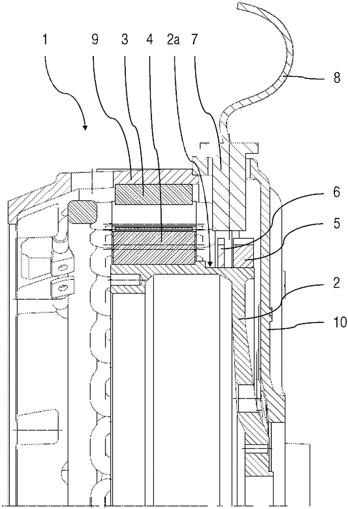
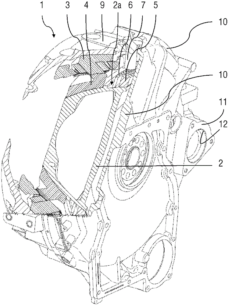
[0018] figure 1 A cross-sectional view of the upper half of a crank starter generator according to one embodiment of the invention is shown. A crank starter generator 1 is positioned between a gearbox and an internal combustion engine (not shown here) in the drive train of a motor vehicle. The crank starter generator includes a CSG housing 9 which may have a splittable configuration. The stator 3 is fixed on the inner periphery of the CSG case 9 . The stator is formed of magnetic steel plates and windings of the stator, the magnetic steel plates are joined to each other and welded to each other, and the windings of the stator are housed inside. Furthermore, the crank starter generator 1 includes a rotor 4 which is fixedly arranged on the cylindrical peripheral surface 2 a of the rotor bracket 2 to rotate therewith. The rotor carrier is part of flywheel 2. A cylindrical peripheral surface 2 a extending in the axial direction is integrally formed on the outer peripheral regi...


PUM


Abstract

The invention relates to a crankshaft starter generator, comprising a stator (3), a rotor (4), a rotor carrier (2) and a starter ring gear (5), which is fixedly connected to the rotor carrier, rotates with the rotor carrier, is arranged on the cylindrical outer surface (2a) of the rotor carrier (2). The crankshaft starter generator further comprises a second crown wheel (6), which is fixedly connected to the rotor carrier, rotates with the rotor carrier, and is arranged on the cylindrical outer surface (2a) of the rotor carrier (2), and thus the crankshaft starter generator is axially derivated relative to the starter crown wheel.

Description

Technical field [0001] The invention involves a crankshaft starter generator described in accordance with the pre -symbolized clauses of claim 1. Background technique [0002] The transmission system module is known in practice. Among them, the motor that can be used as an electric motor and the motor operated as a generator is located between the engine and the gearbox compared to the crankshaft coaxial coaxial.form.Here, the crankshaft starter generator is connected to the crankshaft through the CSG rotor, and the CSG rotor is fixedly connected to the flywheel to rotate with it. The flywheel is set on the crankshaft. [0003] For the operation of a crankshaft starter generator, the rotation position of the rotor relative to the stator is required by the vehicle electronic device or vehicle controller.It is learned from practice to detect the rotation position of the rotor relative to the stator through the additional cup -shaped or pot -shaped components, and the cup -shaped or...

Claims


Application Information

Patent Timeline
IPC IPC(8): F02N15/02F02N11/04
CPCF02N11/006F02N11/04H02K11/215H02K7/006G01D5/2451F16F15/30
Inventor M.戈尔卡
Owner MAN NUTZFAHRZEUGE AG
Features
  • R&D
  • Intellectual Property
  • Life Sciences
  • Materials
  • Tech Scout
  • Unparalleled Data Quality
  • Higher Quality Content
  • 60% Fewer Hallucinations
Learn More