Device and method for reducing hydro-mechanical deep drawing force of large-size plate component

A liquid-filled deep-drawing, large-scale technology, applied in metal processing, metal processing equipment, manufacturing tools, etc., can solve the problems of large reaction force of liquid medium, large equipment tonnage, high energy consumption, and reduce drawing force and equipment. Tonnage reduction and significant economic benefits

Active Publication Date: 2016-05-04
HARBIN INST OF TECH
View PDF9 Cites 37 Cited by
  • Summary
  • Abstract
  • Description
  • Claims
  • Application Information

AI Technical Summary

Problems solved by technology

[0006] The object of the present invention is to provide a device and method for reducing the liquid-filled deep-drawing force of large-sized plate components (the ratio of slab thickness to slab dia...

Method used


Image

  • Device and method for reducing hydro-mechanical deep drawing force of large-size plate component
  • Device and method for reducing hydro-mechanical deep drawing force of large-size plate component
  • Device and method for reducing hydro-mechanical deep drawing force of large-size plate component

Examples


specific Embodiment approach 1

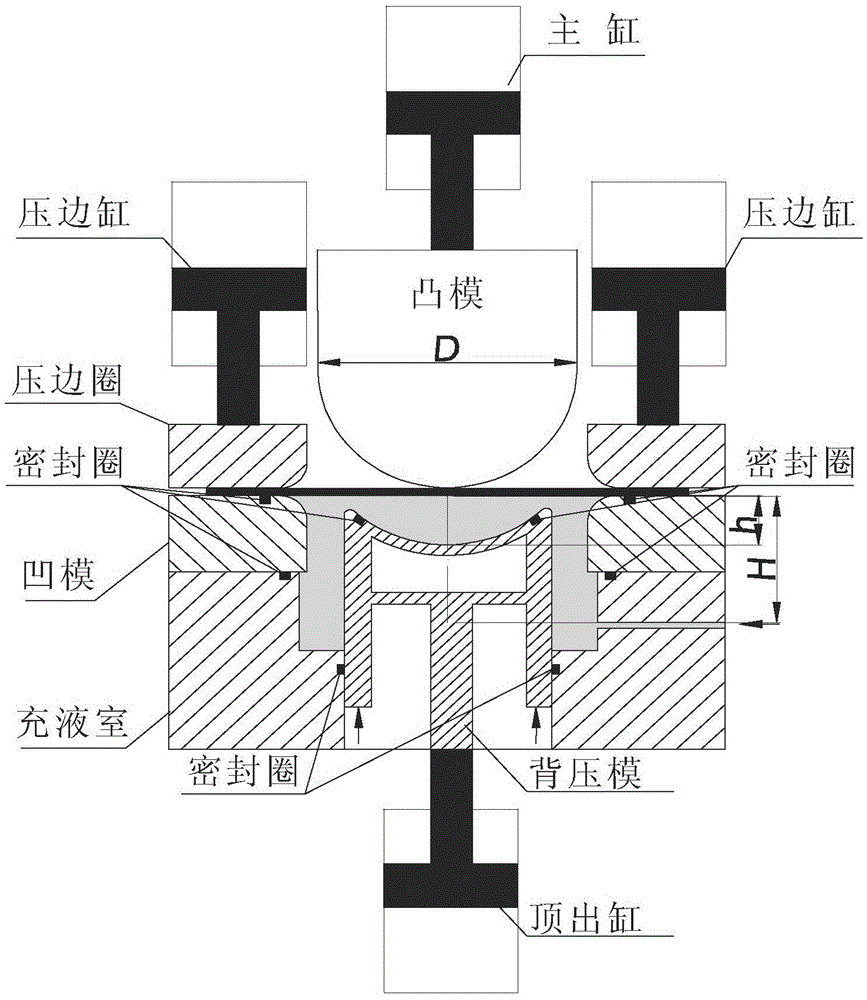
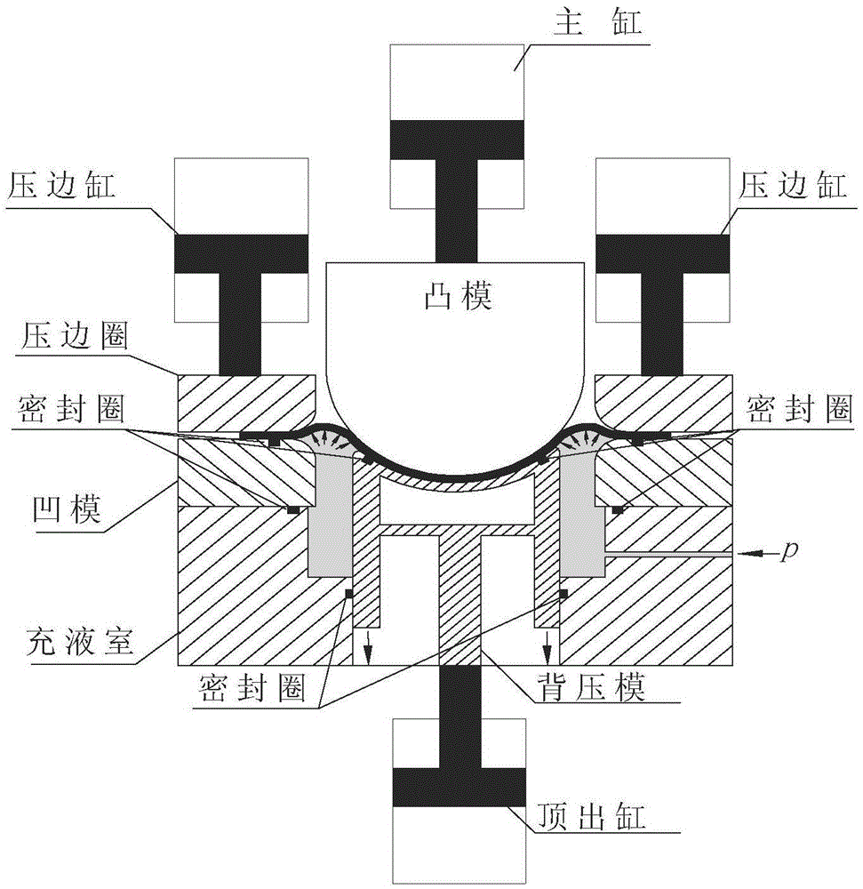
[0026] Specific implementation one: as figure 2 As shown in the figure, the device for reducing the liquid-filled deep drawing force of large-sized plate members in this embodiment includes a punch 1, a female die 2, a blank holder 3, a liquid chamber 4 and a back pressure die 5; the punch 1 and the blank holder 3 is coaxial and the punch 1 can move up and down along the axial through hole of the blank holder 3, the punch 1 is fixed on the master cylinder of the double-action press, the blank holder 3 is located above the female die 2, and the blank holder 3 is fixed on the blank holder cylinder of the double-action press for blank 6 blank holder, the die 2 is located on the upper end surface of the liquid chamber 4, the die 2 and the liquid chamber 4 are fixedly connected, and the liquid chamber 4 is fixed On the work surface of the double-action press, the side wall of the liquid chamber 4 is provided with a liquid injection hole 4-1; , the back pressure die 5 passes throu...

specific Embodiment approach 2

[0030] Specific implementation two: as Figure 5 As shown, the upper part of the back pressure mold in this embodiment is a container frame with an open upper surface, and the interior is filled with a polyurethane pad or elastic rubber 11 . Other components and connection relationships are the same as in the first embodiment. The processing method for liquid-filled deep drawing of the plate member by using the above-mentioned device is the same as that of the first embodiment.

specific Embodiment approach 3

[0031] Specific implementation three: as Image 6 As shown, the bottom of the back press die of this embodiment is supported by springs or nitrogen cylinders and fixed on the table top of the double-action press. Other components and connection relationships are the same as in the first embodiment. The processing method for liquid-filled deep drawing of the plate member by using the above-mentioned device is the same as that of the first embodiment.


PUM


Abstract

The invention provides a device and method for reducing hydro-mechanical deep drawing force of a large-size plate component, and relates to a forming device and method for thin-wall deep-cavity curved-surface plate component in order to solve the problems that during hydro-mechanical deep drawing of the large-size plate component, reactive force of liquid media is large, and accordingly equipment tonnage is large and energy consumption is high. The device comprises male die, an edge pressing ring, a female die, a liquid chamber and a back pressing die. The upper surface of the back pressing die is an inwards concave curved face, the curved face and the part, corresponding to the female die above, of the curved face are identical in shape, and the side wall of the back pressing die can slide up and down along the side wall of a large through hole in the bottom of the liquid chamber. When the male die moves downwards to a certain depth, the lower surface of a slab makes contact with the upper surface of the back pressing die and is completely attached to the upper surface of the back pressing die, the back pressing die moves downwards along with the male die and clamps the slab at the same time, the attached portion of the slab is not affected by high-pressure liquid, only the portion, in the annular area of the outer side of the back pressing die, of the lower surface of the slab is subjected to action of the high-pressure liquid, and hydro-mechanical deep drawing force is reduced because the action area of the high-pressure liquid on the male die is reduced.

Description

technical field [0001] The invention relates to a deep-cavity plate member forming device and method, in particular to a liquid-filled deep-drawing forming device and method for a large-sized thin-walled deep-cavity curved plate member. Background technique [0002] Liquid-filled deep drawing of sheet metal adopts liquid medium instead of mold to transmit load, so that the sheet is pressed against the punch under the pressure of the liquid medium. While controlling the pressure of the liquid medium and the blank holder force, the punch is moved down to pull the sheet into the concave. Die to realize the forming of thin-walled sheet components ( figure 1 - traditional schematic). In the process of liquid-filled deep drawing, the liquid pressure in the liquid chamber is used to make the material against the punch avoid thinning and cracking under the action of "friction retention", and a certain liquid pressure is used to form a "liquid" between the plate and the die. "Lubri...

Claims


Application Information

Patent Timeline
IPC IPC(8): B21D26/021B21D26/031B21D22/22B21C51/00
CPCB21C51/00B21D22/22B21D26/021B21D26/031
Inventor 刘伟徐永超苑世剑
Owner HARBIN INST OF TECH
Why Eureka
Try Eureka