Wear-resistant high-precision self-centering chuck

A self-centering chuck, high-precision technology, applied to chucks, turning equipment, tool holder accessories, etc., can solve the problems of incomplete sealing, small number of teeth, and difficult clamping of disc parts, so as to prolong the service life , The effect of extending the distance of the wire teeth and increasing the number of wire teeth

Inactive Publication Date: 2016-05-04
赵恒源
View PDF1 Cites 1 Cited by
  • Summary
  • Abstract
  • Description
  • Claims
  • Application Information

AI Technical Summary

Problems solved by technology

But there are still the following problems: First, although the concentricity of single-group cylinder, cone, and ball pinball bearings is good, there will always be gaps in the process of wear and tear, so according to his design, it cannot better prevent the coil wire The left, right, up and down movement of the body in the chuck body brings errors to the repeated clamping of the workpiece
Another disadvantage is that there is insufficient disconnection at the bottom of the I-shaped guide rail of the claw, because the distance between the bottom of the I-shaped guide rail of the claw and the teeth of the claw is too short, so the number of teeth is too small, and the claw is easy to fall off after being stressed.
The second is that the seal is not complete, because the garbage mainly enters the chuck body from two places, one is the place where the wire body is connected to the chuck body, and the second is the place where the garbage plate is connected to the chuck body, and the garbage enters Seriously affects the accuracy of the chuck's repeated clamping of the workpiece
The third is that the lubrication system is not designed, and the fourth is that the design of the claw part needs to be improved.
There are other self-centering chucks that use sliding friction and disc parts are not easy to clamp, etc.
In terms of design, this seriously hinders the service life of the chuck and the accuracy of repeated clamping workpieces

Method used


Image

  • Wear-resistant high-precision self-centering chuck
  • Wear-resistant high-precision self-centering chuck
  • Wear-resistant high-precision self-centering chuck

Examples


Embodiment Construction

[0019] Below in conjunction with accompanying drawing, this design is described in detail.

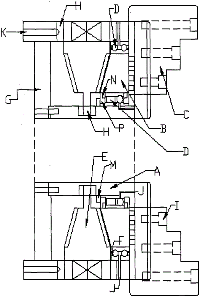
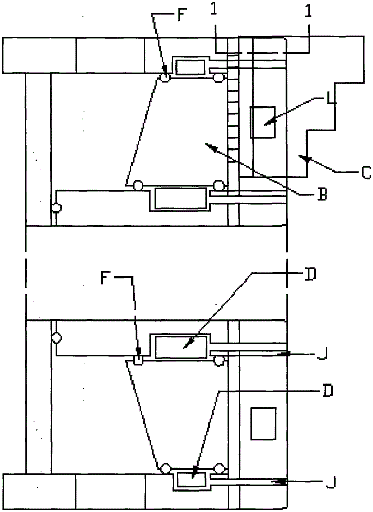
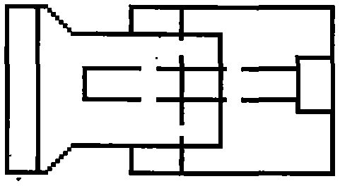
[0020] Such as Figure 1 to Figure 23 Shown; a wear-resistant high-precision self-centering chuck. It consists of a chuck body, a coil body, claws, rolling guides, bevel gears, sealing rings or sealing tapes or sealing rings, side seals, garbage baffles, balls or bearings or bushings, claw fastening screws , lubricating oil circuit, anti-out pin, oil storage block, cylindrical pins or conical pins or ball pins or oval pins, fastening ring or circlip, outer ring of magnetic block, cast iron block, copper sheet, permanent magnet and other components. The chuck body is a sunken cavity formed between the outer convex and the inner boss, and a bevel gear is installed in the sunken cavity. The bevel gear can be a traditional bevel gear or a new bevel gear as shown in the figure. Bevel gear, the two ends of the bevel gear are equipped with marbles or bushings or bearings, which are tightly ...


PUM


Abstract

The invention discloses a wear-resistant high-precision self-centering chuck which comprises chuck bodies, bevel gears mounted in the chuck bodies, wire coiling bodies, garbage baffles, sealing rings or sealing tapes, lubricating pieces and magnetic blocks, wherein the multiple types of rolling or combined type rolling guide rails are arranged at both ends of the bevel gears, the inner and outer diameter parts (the inner diameter parts and the outer diameter parts) and the end surfaces of the wire coiling bodies, or on the chuck bodies; the lubricant passage ways or a lubricating oil is arranged at friction parts as well as parts, provided with the rolling guide rails, of the chuck bodies; multiple types of sliding guide rails which are super large in contact area and convenient in precision repair and claws which are convenient in precision repair are arranged on the end surfaces of the chuck bodies; the garbage baffles have sealing property; the sealing rings or sealing tapes are arranged at the inner and outer diameter parts of the chuck bodies or at the garbage baffles; the lubricating pieces are arranged in the guide rails arranged on the end surfaces of the chuck bodies; the magnetic blocks are arranged on the claws and capable of easily clamping disc parts to be flat. The wear-resistant high-precision self-centering chuck has the advantages that the wear precision can be conveniently repaired, the cost is low, the precision is high, high durability is achieved, the production cost is reduced, the production efficiency is improved, and the original generation chuck can be replaced, therefore the chuck is an ideal wear-resistant high-precision self-centering chuck.

Description

technical field [0001] The wear-resistant and high-precision self-centering chuck belongs to the field of machine manufacturing, and in particular relates to the self-centering chuck of a clamping accessory. Background technique [0002] In the field of mechanical manufacturing and processing, the commonly used fixture is a self-centering chuck. It is composed of chuck body, bevel gear, disc wire body, jaws, garbage plate, and screws. We know that the main components that are mainly responsible for the repeated clamping accuracy of the workpiece depend on the tolerance level of the fit between the wire body and the chuck body and the tolerance level between the jaws and the guide rail on the end surface of the chuck body. After reading a large amount of Chinese literature, I found that, in addition to the patent No. ZL201520482151.5, cylinders, cones, and ball bearings are placed at the inner diameter of the boss in the chuck and the inner diameter of the wire, and a bearin...

Claims


Application Information

Patent Timeline
IPC IPC(8): B23B31/169
CPCB23B31/16083B23B2231/32
Inventor 赵恒源
Owner 赵恒源
Why Eureka
Try Eureka