Laser forming machine

A forming machine and laser technology, applied in the field of additive manufacturing, can solve the problems of increased section size of forming cylinder, inconvenient operation, high forming surface height, etc.

Active Publication Date: 2016-05-04
BEIJING HK PRECISIONS CO LTD
View PDF6 Cites 26 Cited by
  • Summary
  • Abstract
  • Description
  • Claims
  • Application Information

AI Technical Summary

Problems solved by technology

The existing selective laser powder sintering molding machine mainly emits laser light from a laser, which is focused on the molding surface through beam expansion and scanning galvanometer reflection, and performs selective laser sintering and solidification on the cross section of the part, and then the piston of the molding cylinder is lowered by one layer to re-cover A layer of powder, so that the parts are processed by laser sintering and solidification layer by layer. As the size of the manufactured parts increases, not only the section size of the forming cylinder is required to be increased, but also the piston stroke of the forming cylinder is required to be larger. The existing piston drive methods are: There are two types, one is driven by an electric push rod installed under the piston. When the stroke of the piston is larger in this way, it will lead to a high height of the forming surface, high equipment, and inconvenient operation; the second is driven by a side screw , so that when the piston stroke is large, the forming surface can still be of appropriate height, but a long groove for connecting the piston needs to be opened on the side wall of the forming cylinder, and the long groove is sealed with a steel belt. During long-term use, the steel belt Will be damaged and cause powder leakage, which will affect the reliable and stable operation of the equipment

Method used


Image

  • Laser forming machine

Examples


Embodiment Construction

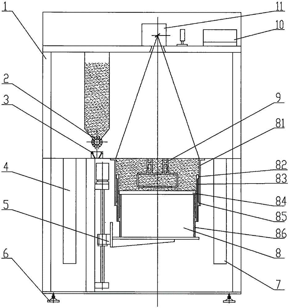
[0019] refer to figure 1 Shown, this embodiment is a two-section telescopic cylinder form. The outermost telescopic cylinder 81 is fixed to the worktable and the frame, and the upper end between the outermost telescopic cylinder 81 and the innermost telescopic cylinder 83 is sealed by a seal 82, and the lower end is guided by a cylinder moving guide device 85, and the piston is guided by the piston. The motion drive system drives the innermost telescopic cylinder 83 to move up and down, which not only ensures the reliable sealing of the forming cylinder, but also, under the same height of the working table, the piston stroke can be lengthened compared with the usual single cylinder, so that Parts with larger dimensions in the height direction can be processed.

[0020] What has been described above are only preferred embodiments of the present invention. It should be pointed out that for those skilled in the art, without departing from the principle and core idea of ​​the pr...


PUM


Abstract

The invention relates to a laser forming machine. The laser forming machine comprises a rack (1), a feed system (2), a powder laying hopper, a motion system (3), a discharging and collecting box, forming cylinders, a forming cylinder piston motion drive system and an optical system, wherein the optical system is composed of a laser device, a scanning galvanometer and a reflecting and focusing mirror. The laser forming machine is characterized in that the forming cylinders are more than two telescopic cylinders. As the telescopic forming cylinders are adopted, operating strokes of forming cylinder pistons can be increased under the circumstance of not increasing the height of a working table board and the height of equipment, the size of machined parts is increased, and operability and reliability of the equipment are improved.

Description

technical field [0001] The invention relates to a laser molding machine, in particular to an area-selective powder laser sintering molding equipment, which belongs to the technical field of additive manufacturing. Background technique [0002] At present, 3D printing has been widely recognized and applied. Selective powder laser sintering is a molding method in 3D printing technology. The existing selective laser powder sintering molding machine mainly emits laser light from a laser, which is focused on the molding surface through beam expansion and scanning galvanometer reflection, and performs selective laser sintering and solidification on the cross section of the part, and then the piston of the molding cylinder is lowered by one layer to re-cover it. A layer of powder, so that the parts are processed by laser sintering and solidification layer by layer. As the size of the manufactured parts increases, not only the section size of the forming cylinder is required to be i...

Claims


Application Information

Patent Timeline
Patent Type & Authority Applications(China)
IPC IPC(8): B29C67/00B33Y30/00
Inventor 李全贵
Owner BEIJING HK PRECISIONS CO LTD
Why Eureka
Try Eureka