
Continuous garbage compression dehydration device

A dehydration device and garbage compression technology, which is applied in the direction of presses, material forming presses, manufacturing tools, etc., can solve the problems of fixed compression force, poor dehydration effect, and uneven compactness of garbage, and achieve continuous feeding Material discharge, enhanced compression dehydration effect, adjustable dehydration rate

Active Publication Date: 2017-10-27
JIANGSU HUAHONG TECH STOCK +1
View PDF1 Cites 0 Cited by
  • Summary
  • Abstract
  • Description
  • Claims
  • Application Information

AI Technical Summary

Problems solved by technology

[0007] In order to solve the problems of fixed compression force, uneven compactness of garbage and poor dehydration effect in the garbage compressor in the prior art

Method used


Image

  • Continuous garbage compression dehydration device
  • Continuous garbage compression dehydration device
  • Continuous garbage compression dehydration device

Examples


Embodiment Construction

[0039] The present invention will be further described below in conjunction with the accompanying drawings and specific embodiments.

[0040] Continuous garbage compression dehydration device,

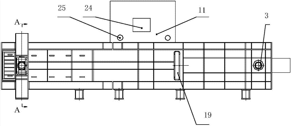
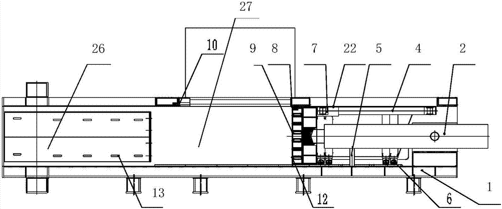
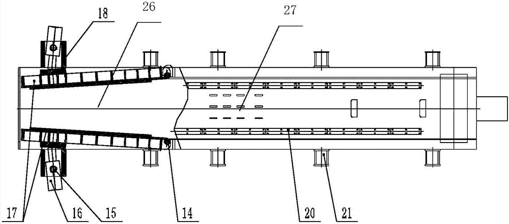
[0041] Such as Figure 1~5As shown, the device for continuous dehydration of household garbage in the present invention includes: a hollow cylindrical dehydration chamber surrounded by a frame 1, a main pressure oil cylinder 2 and a feeding device, and the dehydration chamber is composed of a pre-compression chamber 27 and the main pressure chamber 26; the top of the pre-compression chamber 27 has a feeding port 11, the feeding device is arranged above the feeding port 11, the main pressure cylinder 2 is installed at one end of the pre-compression chamber 27, and the main pressure cylinder 2 is connected to the main pressure chamber. The head 9 and the main pressure head 9 are located inside the pre-compression chamber, the direction of movement of the piston rod of the main pressure ...


PUM


Abstract

The invention discloses a continuous type garbage compressing and dewatering device. The continuous type garbage compressing and dewatering device comprises a hollow barrel-shaped dewatering cabin body, a main pressing oil cylinder and a feeding device, and the hollow barrel-shaped dewatering cabin body is enclosed by a rack. The dewatering cabin body is composed of a pre-pressing cabin and a main pressing cabin. A feeding inlet is formed in the top of the pre-pressing cabin. The feeding device is arranged above the feeding inlet. The main pressing oil cylinder is installed at one end of the pre-pressing cabin and connected with a main pressing head. The main pressing head is located inside the pre-pressing cabin. The motion direction of a piston rod of the main pressing oil cylinder is parallel to the axis direction of the pre-pressing cabin. The other end of the pre-pressing cabin is connected with the main pressing cabin. The main pressing cabin comprises a top plate, a bottom plate and two side pressing plates, wherein the top plate is fixedly connected with the pre-pressing cabin, and the two side pressing plates are hinged to the pre-pressing cabin. The outlet end of the main pressing cabin is a discharging outlet. The side pressing plates are driven by side pressing oil cylinders. The motion direction of piston rods of the side pressing oil cylinders is perpendicular to the axis direction of the pre-pressing cabin. According to the continuous type garbage compressing and dewatering device, the structure is simple, feeding and discharging can be conducted continuously, pressure is uniform and controllable, and operation is flexible and variable.

Description

technical field [0001] The invention discloses a continuous garbage compression and dehydration device, relates to domestic garbage compression and dehydration treatment equipment, and belongs to the field of mechanical equipment. Background technique [0002] Waste incineration has gradually become an effective way to reduce waste and recycle waste. However, the water content of waste has a great impact on waste incineration process, energy recovery efficiency and economic benefits. The moisture content of the raw waste entering the factory in most areas of my country is greater than 50%, and even in some humid climates or along the river and coastal areas, the moisture content of the raw waste entering the factory is greater than 60%, so it needs to be dehydrated before it is suitable for entering the furnace Combustion, the commonly used garbage dehydration treatment methods are fermentation dehydration and compression dehydration. The treatment method of fermentation deh...

Claims


Application Information

Patent Timeline
Patent Type & Authority Patents(China)
IPC IPC(8): B30B9/04B30B11/26B30B15/16B30B15/00
CPCB30B9/04B30B9/047B30B11/265B30B15/00B30B15/16
Inventor 胡品龙孙锡健符杰邬燕峰
Owner JIANGSU HUAHONG TECH STOCK
Learn More