
Novel feeding device for winding machine

A feeding device and winding machine technology, applied in packaging, conveyors, conveyor objects, etc., can solve the problems of labor, poor flexibility, high work intensity, etc., and achieve fast feeding and feeding speed, feeding neatly, The effect of shortening the winding time

Active Publication Date: 2016-05-04
LANGXI ZHENHAI MACHINERY
View PDF6 Cites 2 Cited by
  • Summary
  • Abstract
  • Description
  • Claims
  • Application Information

AI Technical Summary

Problems solved by technology

[0002] Roll up the quilt / pillow core tightly and put it into a packaging bag, usually manually or semi-automatically, that is, manual loading, machine winding and packaging, and the size of the machine packaging cannot be adjusted, and manual packaging of the quilt or pillow core is time-consuming , laborious, high work intensity, and low work efficiency, and the packaging of the quilt can only be packed manually at a fixed point, which cannot be easily moved, and the flexibility is poor. It is necessary to place the packing box next to the quilt or pillow to be packed , and then manually wind it and place it in the packing box. This kind of packaging is relatively rigid, and it cannot form a production and transportation line. To be able to form an automated and mechanized roll quilt and roll pillow core, it is necessary to realize automation. material, and whether the feeding is orderly directly affects the quality of subsequent winding

Method used


Image

  • Novel feeding device for winding machine
  • Novel feeding device for winding machine
  • Novel feeding device for winding machine

Examples


Embodiment Construction

[0023] In order to enable those skilled in the art to better understand the technical solution of the present invention, the technical solution of the present invention will be further described below in conjunction with the accompanying drawings and embodiments.

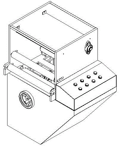
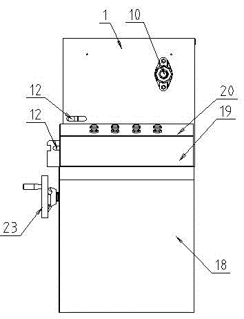
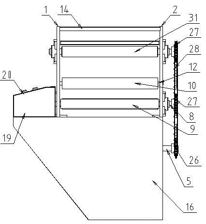
[0024] Refer to attached Figure 1-8 The new feeding device of a winding machine shown includes a support base, which is a frame structure composed of a front side plate 16, a rear side plate 17, an inclined side plate 18 and a vertical plate, and the support base An electrical box 19 is provided on the upper front end surface, and a conveying and feeding device is provided on the upper rear surface of the support base, and the conveying and feeding device includes a transmission mechanism, an adjusting mechanism, a conveying mechanism, a control mechanism and a feeding box; The box is set on the support base, the transmission mechanism is set in the support base, the transmission mechanism is connected with the tra...


PUM


Abstract

The invention discloses a novel feeding device for a winding machine. The novel feeding device comprises a support base, the front end face of the support base is provided with an electric appliance box, the back end face of the support base is provided with a material conveying feeding device, and the material conveying feeding device comprises a transmission mechanism, a regulating mechanism, a conveying mechanism, a control mechanism and a feeding box; the feeding box is arranged on the support base, the transmission mechanism is arranged in the support base, the conveying mechanism is in transmission connection with the transmission mechanism, the conveying mechanism is arranged in the feeding box, and the regulating mechanism is arranged over the transmission mechanism. The feeding device is a mechanism which can perform automatic feeding after manual packaging is changed into automatic packaging, and the mechanism can perform feeding in a conveying mode, perform smoothing operation on products to be packaged through a horizontal conveyor belt and an inclined conveyor belt and enable the products to be packaged to have the smooth shape before being wound.

Description

technical field [0001] The invention relates to a winding machine, in particular to a novel feeding device for the winding machine. Background technique [0002] Roll up the quilt / pillow core tightly and put it into a packaging bag, usually manually or semi-automatically, that is, manual loading, machine winding and packaging, and the size of the machine packaging cannot be adjusted, and manual packaging of the quilt or pillow core is time-consuming , laborious, high work intensity, and low work efficiency, and the packaging of the quilt can only be packed manually at a fixed point, which cannot be easily moved, and the flexibility is poor. It is necessary to place the packing box next to the quilt or pillow to be packed , and then manually wind it and place it in the packing box. This kind of packaging is relatively rigid, and it cannot form a production and transportation line. To be able to form an automated and mechanized roll quilt and roll pillow core, it is necessary ...

Claims


Application Information

Patent Timeline
Patent Type & Authority Applications(China)
IPC IPC(8): B65B35/00B65G23/06B65G39/10
CPCB65B35/00B65G23/06B65G39/10B65G2201/0214
Inventor 陈功
Owner LANGXI ZHENHAI MACHINERY
Learn More